

Solenoid actuator
a solenoid actuator and actuator technology, applied in the direction of magnets, valve operating means/release devices, magnetic bodies, etc., can solve the problems of affecting the operation of the valve sha
- Summary
- Abstract
- Description
- Claims
- Application Information
AI Technical Summary
Benefits of technology
Problems solved by technology
Method used
Image

Examples
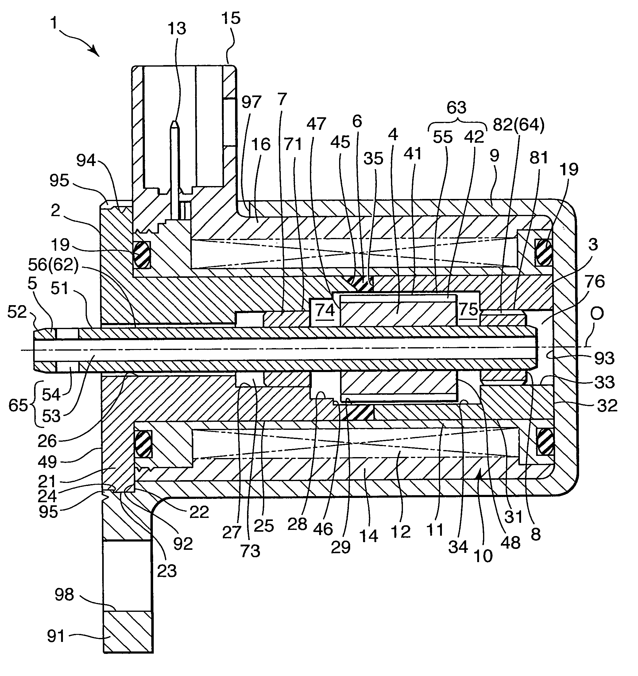
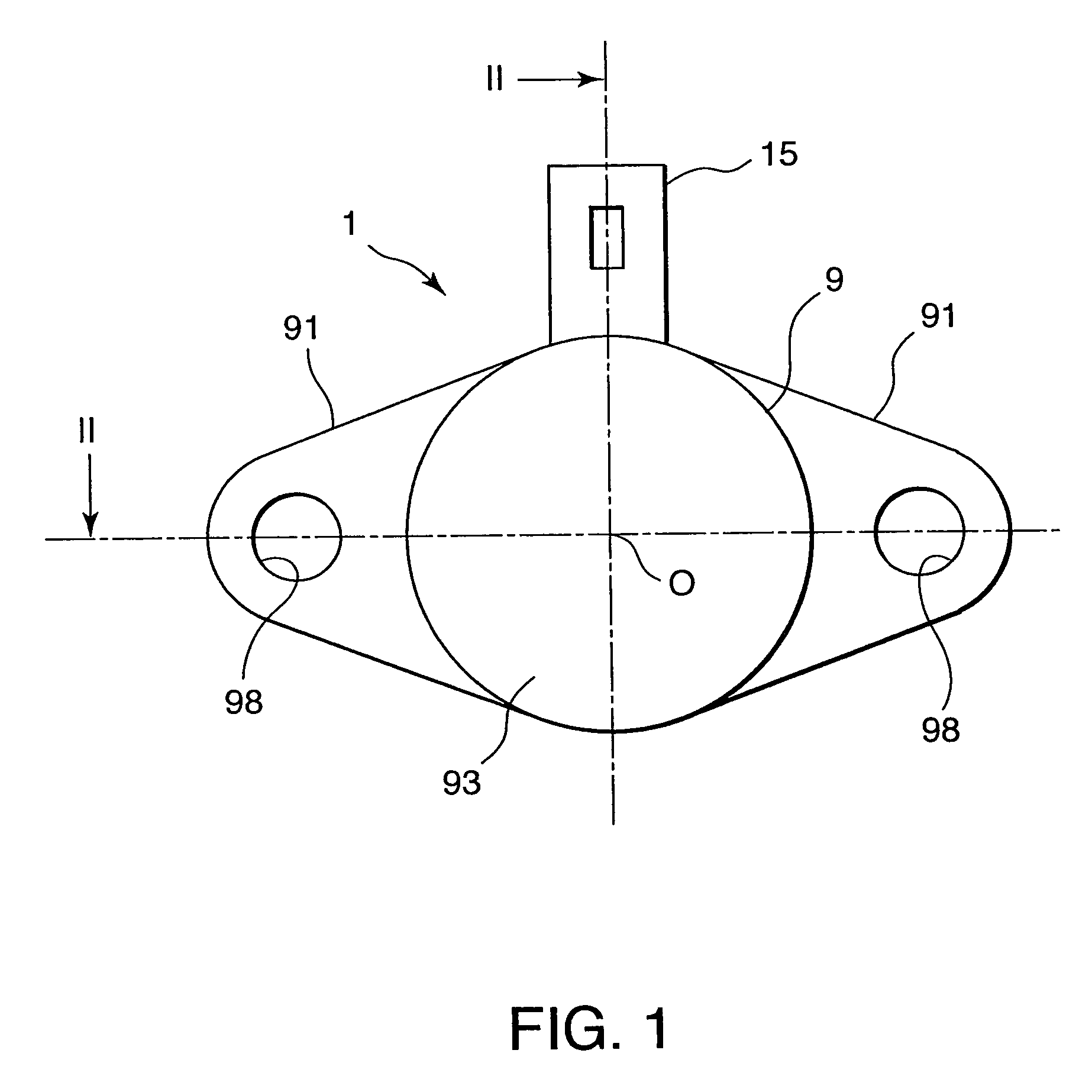
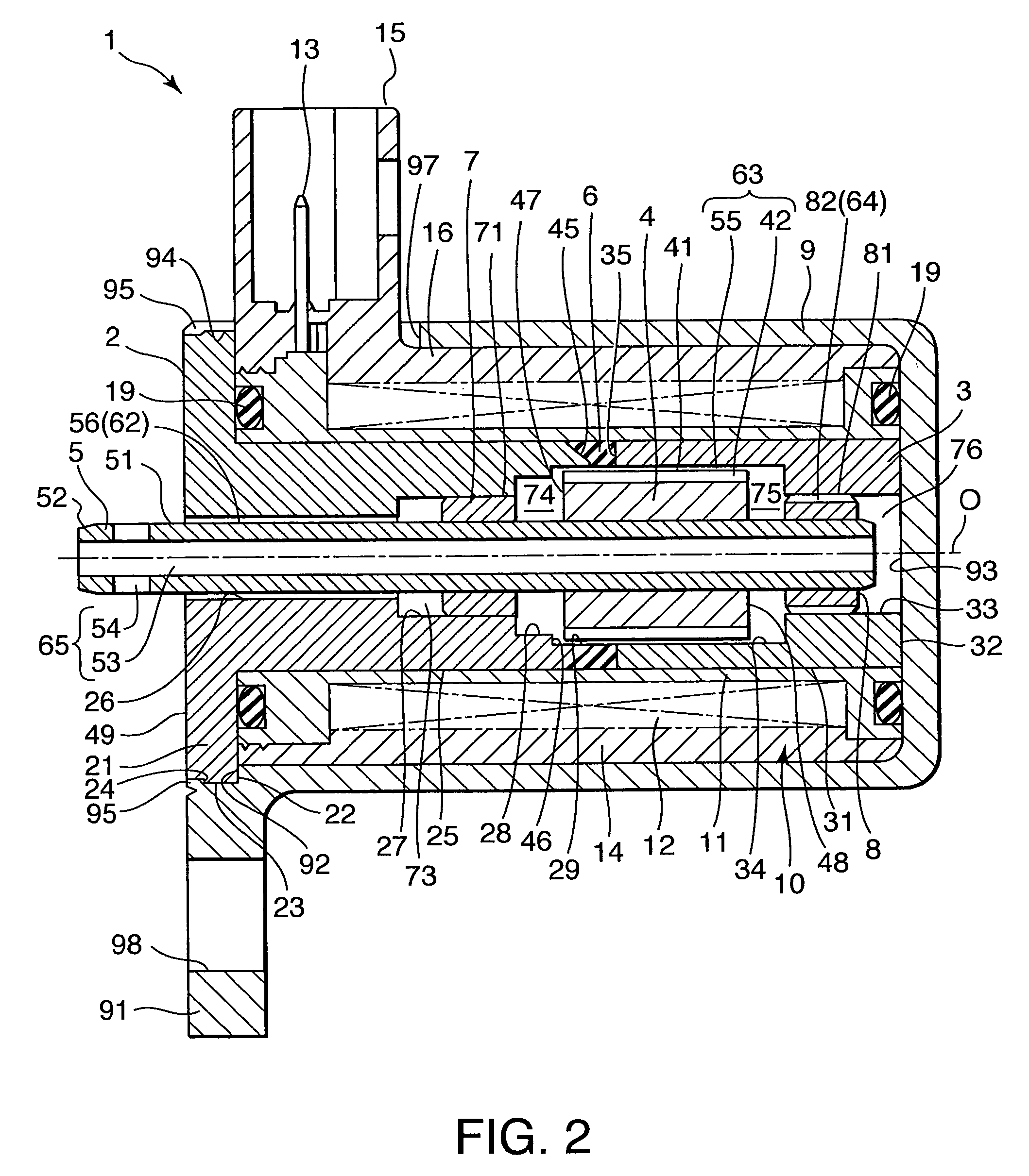
first embodiment
[0076]All these embodiments are provided with an identical pressure transmitting structure to the first embodiment shown in FIGS. 1-3 to prevent a difference in the pressures acting on the second bearing 8. Further, these embodiments are provided with special constructions to prevent contaminant from invading the gap 55 from the plunger front chamber 74 or the plunger rear chamber 75.
second embodiment
[0077]First, referring to FIG. 4, this invention will be described.
[0078]Components of this embodiment that have the same construction as those of the first embodiment shown in FIGS. 1-3 are given identical component numbers, and their description is herein omitted.
[0079]A solenoid actuator 1 according to this embodiment comprises a cylindrical cover 83 made of non-magnetic material to cover the outer circumferential surface 41 of the plunger 4. The annular gap 55 is formed between a cylindrical wall surface formed by the inner circumferential surface 34 of the sleeve 3, the inner circumferential surface of the gap filler 6 and the inner circumferential surface 29 of the base 2, and the cover 83. The annular gap 55 forms the plunger exterior oil passage 63 connecting the plunger front chamber 74 to the plunger rear chamber 75.
[0080]The cover 83 comprises a cylindrical portion 84 covering the outer circumferential surface 41 of the plunger 4 and a front end portion 85 which is bent i...
third embodiment
[0086]Referring to FIG. 5, this invention will be described.
[0087]Components of this embodiment that have the same construction as those of the first and the second embodiments are given identical component numbers, and their description is herein omitted.
[0088]According to this embodiment, the cover 83 comprises a projecting portion 86 which is continuous with the cylindrical portion 84 and projects into the plunger front chamber 74 instead of the front end portion 85 of the second embodiment covering the outer part 47a of the front end face 47 of the plunger 4. The diameter of the projecting portion 86 is identical to that of the cylindrical portion 84.
[0089]The front end face 47 of the plunger 4 is exposed to the plunger front chamber 74 on the inner side of the projecting portion 86. The projecting portion 86 prevents contaminant adhered to the front end face 47 of the plunger 4 from invading the plunger exterior oil passage 63 on the outside of the cylindrical portion 84. As a ...
PUM
| Property | Measurement | Unit |
|---|---|---|
| magnetic force | aaaaa | aaaaa |
| pressures | aaaaa | aaaaa |
| magnetic field | aaaaa | aaaaa |
Abstract
Description
Claims
Application Information