Solenoid actuator

a solenoid actuator and actuator technology, applied in the direction of positive displacement liquid engines, magneto-body engines, piston pumps, etc., can solve the problems of increasing the adverse effect of the solenoid actuator, so as to prevent deposits and increase the sliding resistance of the shaft.

Inactive Publication Date: 2013-06-25
KYB CORP
View PDF28 Cites 17 Cited by
  • Summary
  • Abstract
  • Description
  • Claims
  • Application Information

AI Technical Summary

Benefits of technology

[0009]It is therefore an object of this invention to prevent deposits of a contaminant in the strong magnetic field portion without increasing the sliding resistance of the shaft.

Problems solved by technology

However, the above annular member and ring filter are likely to come into contact with the shaft, causing a sliding resistance of the shaft to increase.
As a result, the response of the solenoid actuator may be affected adversely.

Method used


Image

  • Solenoid actuator
  • Solenoid actuator
  • Solenoid actuator

Examples


second embodiment

[0077]Referring to FIG. 4, this invention will be described.

first embodiment

[0078]Components of this embodiment that have the same construction as those of the first embodiment shown in FIGS. 1-3 are given identical component numbers and their description is herein omitted.

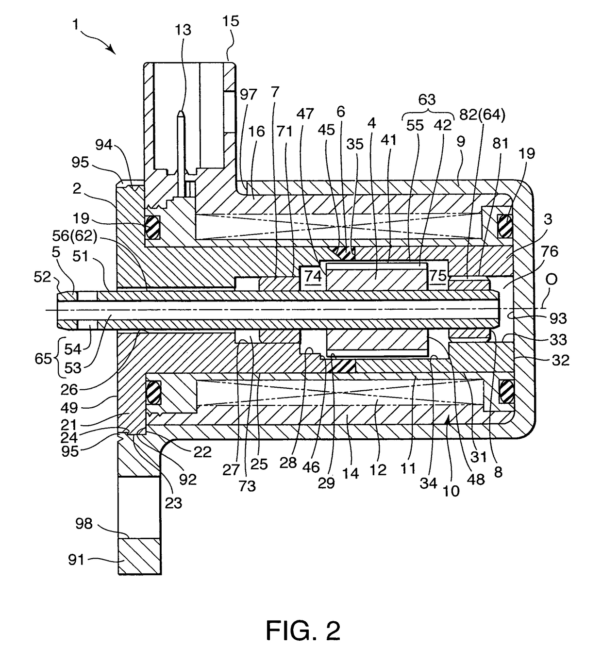
[0079]In a solenoid actuator 1 according to this embodiment, the shaft 5 is made of a solid material and the shaft-penetrating oil passage 65 constituted by the lateral through-hole 54 and the longitudinal through-hole 53 of the first embodiment is not provided.

[0080]A plurality of grooves 72 are formed on the outer circumferential surface 71 of the first bearing 7 in parallel with the center axis O. The grooves 72 forms a first bearing oil passage 68 connecting the first bearing first bearing front chamber 73 to the plunger front chamber 74.

[0081]A cylindrical part 20 projecting from the flange 21 towards the hydraulic equipment is formed on the base 2. The cylindrical part 20 is fitted into a fitting hole of the hydraulic equipment. An O-ring 18 is fitted onto an outer circumferential s...


PUM

PropertyMeasurementUnit
displacementaaaaaaaaaa
magnetic forceaaaaaaaaaa
magnetic pathaaaaaaaaaa

Abstract

A solenoid actuator (1) attached to hydraulic equipment comprises a shaft (5) connected to the hydraulic equipment, a plunger (4) fixed to the shaft (5), a coil (12) which magnetically drives the plunger (4), and a first bearing (7) and a second bearing (8) supporting the shaft (5) on either sides of the plunger (4). A plunger front chamber (74) is formed between the first bearing (7) and the plunger (4), and a plunger rear chamber (75) is formed between the plunger (4) and the second bearing (8). By providing a plunger exterior oil passage (63) on the outside of the plunger (4) to connect the plunger front chamber (74) to the plunger rear chamber (75), working oil flows through the plunger exterior oil passage (63) every time the plunger (4) strokes, thereby preventing a deposit of contaminant on the plunger (4) without increasing a stroke resistance of the plunger (4).

Description

FIELD OF THE INVENTION[0001]This invention relates to a solenoid actuator which drives a shaft axially using a magnetic force created by a solenoid.BACKGROUND OF THE INVENTION[0002]A solenoid actuator for driving hydraulic equipment such as a valve is constituted, for example, by the following members.[0003]Specifically, two cylindrical magnetic path forming members made respectively in a cylindrical form are arranged coaxially with a gap provided there-between in an axial direction, and a plunger made of a magnetic material is disposed on the inside of the magnetic path forming members. A coil provided on the outside of the magnetic path forming members is energized to form a magnetic path through the magnetic path forming members. According to this arrangement, magnetic flux transfer between the two magnetic path forming members is performed via the plunger such that the plunger is driven in the axial direction by a magnetic force, and a shaft fixed to the plunger performs a linea...

Claims


Application Information

Patent Timeline
Patent Type & Authority Patents(United States)
IPC IPC(8): F16K31/02H01F5/00H01F3/00
CPCH01F7/1607H01F2007/085H01F2007/163
Inventor YAMAGATA, HIDEKIHOSOGAI, MAMORUTSUCHIYA, HIDEKIMIYA, YOSHIHARUFUJITA, TOMOYUKIAKATSUKA, KOICHIROYAZAKI, KENJI
Owner KYB CORP
Why Eureka
Try Eureka