Contact and method for manufacturing metal component

a metal component and contact technology, applied in the direction of contact member manufacturing, coupling device connection, engagement/disengagement of coupling parts, etc., can solve the problem of connecting b>11/b> receiving vibrations

Active Publication Date: 2013-02-21
ORMON CORP
View PDF7 Cites 4 Cited by
  • Summary
  • Abstract
  • Description
  • Claims
  • Application Information

AI Technical Summary

Benefits of technology

[0010]One or more embodiments of the present invention provides a contact capable of reliably coming into electrical contact and mechanical contact with the other member. Further, one or more embodiments of the present invention provides a method for manufacturing metal components including the contact.

Problems solved by technology

However, there are cases where the connector 11 receives vibrations depending on its application.

Method used


Image

  • Contact and method for manufacturing metal component
  • Contact and method for manufacturing metal component
  • Contact and method for manufacturing metal component

Examples


Embodiment Construction

[0049]Hereinafter, embodiments of the present invention will be described with reference to the attached drawings. However, the following embodiments of the present invention are not restrictive, and a variety of changes in design can be made within the range not deviating from the gist of the present invention. In embodiments of the invention, numerous specific details are set forth in order to provide a more thorough understanding of the invention. However, it will be apparent to one of ordinary skill in the art that the invention may be practiced without these specific details. In other instances, well-known features have not been described in detail to avoid obscuring the invention.

[0050](Structure of Contact)

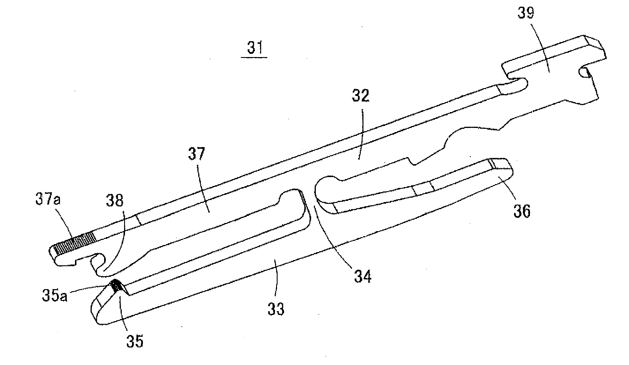
[0051]FIG. 3 is a perspective view of a contact 31 according to an embodiment of the present invention, which is represented in a vertically inverted state. This contact 31 is a minute contact terminal produced by electroforming. FIGS. 4(A) and 4(B) are expanded views of pa...


PUM

PropertyMeasurementUnit
widthaaaaaaaaaa
radiusaaaaaaaaaa
radiusaaaaaaaaaa

Abstract

A method for manufacturing a metal component includes the steps of forming a resist film on a surface of an electrode plate, making the resist film exposed to light by use of a photomask having a mask pattern, in at least part of a rim of which a fine concavity and convexity are drawn, developing the resist film, to form an opening for molding in the resist film, and epositing an electroforming material by electroforming inside the opening for molding, to mold the material.

Description

BACKGROUND[0001]1. Technical Field[0002]The present invention relates to a contact and a method for manufacturing a metal component. The present invention relates to a contact that is incorporated into a housing to form a connector, and a method for manufacturing a metal component usable for manufacturing the contact.[0003]2. Background Art[0004]Patent Document 1 discloses a connector with a configuration shown in FIGS. 1(A) and 1(B). Two kinds of contacts (contact terminals) are incorporated into a housing 12 of this connector 11. FIG. 2 shows one of contacts 21. In this contact 21, a fixing piece 22 and a movable piece 23 are almost in parallel, and the fixing piece 22 and the movable piece 23 are connected by a connecting section 24 vertical to both pieces 22, 23. A movable contact point section 25 is provided on the under surface of the front end of the movable piece 23, and the rear end of the movable piece 23 serves as an operation receiving section 26 that receives an action ...

Claims


Application Information

Patent Timeline
Patent Type & Authority Applications(United States)
IPC IPC(8): H01R13/62H01R13/40C25D1/00H01R13/02
CPCH01R12/88H01R12/778H01R12/77H01R43/16
Inventor YOSHIDA, HITOSHIYOSHIOKA, HIDEKAZUSUZUMURA, TAKAAKIKOYAMA, JIRO
Owner ORMON CORP
Why Eureka
Try Eureka