Radiographic imaging control apparatus using multi radiation generating apparatus

a technology of radiation generating apparatus and control apparatus, which is applied in the direction of patient positioning for diagnostics, instruments, applications, etc., can solve the problems of image quality degradation and image quality degradation, and achieve the effect of suppressing image quality degradation

Inactive Publication Date: 2011-07-12
CANON KK
View PDF35 Cites 40 Cited by
  • Summary
  • Abstract
  • Description
  • Claims
  • Application Information

AI Technical Summary

Benefits of technology

[0010]It is an object of the present invention to provide a control apparatus capable of solving the above-described problems, suppressing degradation in image quality due to an increase in the cone angle, and setting an appropriate irradiation dose for each region of a patient, and a control method thereof.
[0011]It is another object of the present invention to provide a control apparatus that suppresses the influence of radiation from an adjacent radiation generating device.

Problems solved by technology

However, it has been pointed out that an increase in the cone angle in the Z-axis direction of X-ray irradiation increases the influence of scattering rays and errors in reconstruction calculations, resulting in degradation of image quality.

Method used


Image

  • Radiographic imaging control apparatus using multi radiation generating apparatus
  • Radiographic imaging control apparatus using multi radiation generating apparatus
  • Radiographic imaging control apparatus using multi radiation generating apparatus

Examples


first embodiment

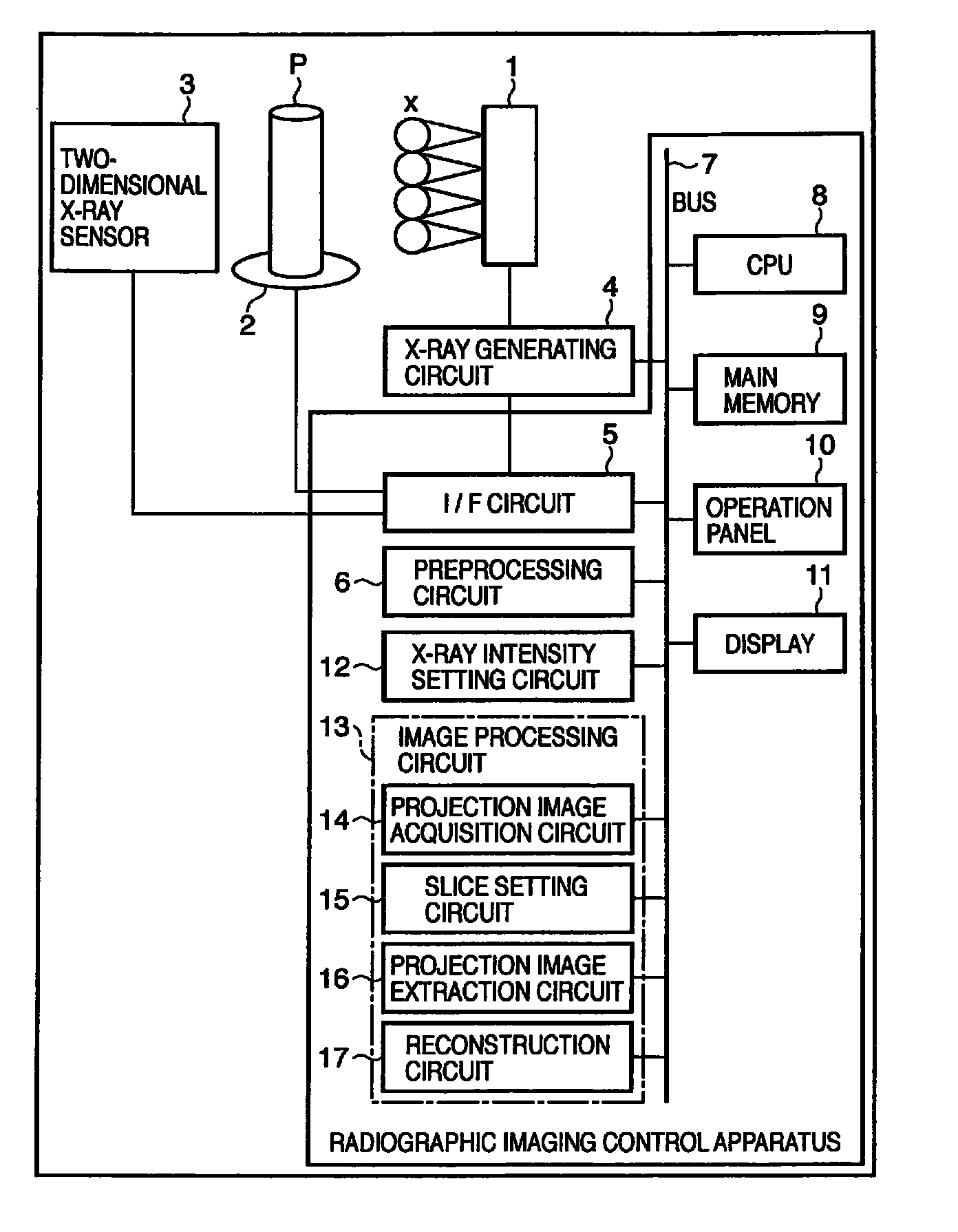
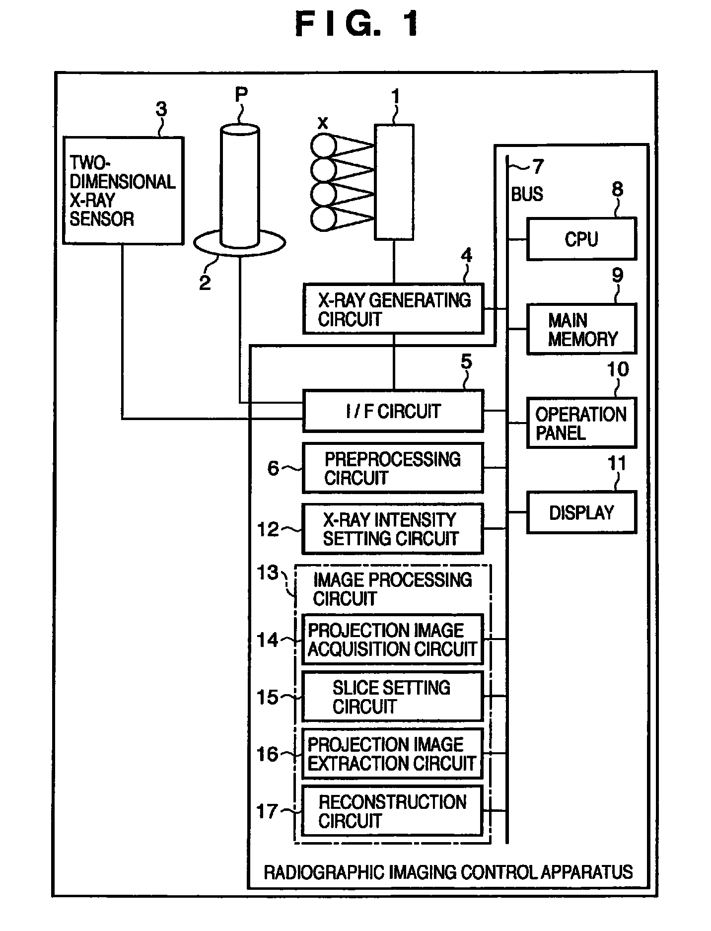
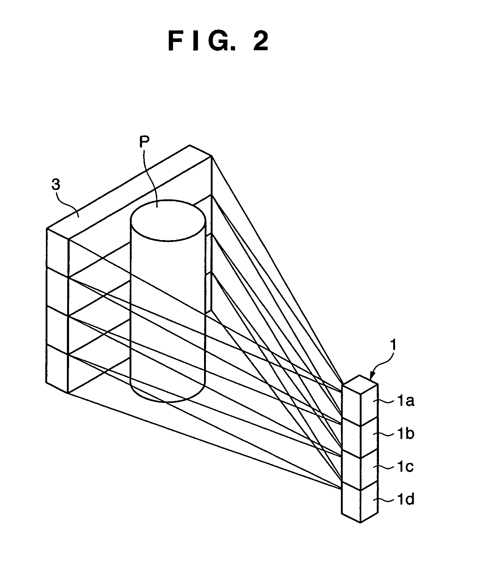
[0034]FIG. 1 shows a system including a radiographic imaging control apparatus according to the first embodiment. A multi X-ray generating apparatus 1 including a plurality of X-ray generating devices which are one-dimensionally arranged irradiates a two-dimensional X-ray sensor 3 with an X-ray beam x that is radiation. The X-ray beam x passes through a patient (object) P on a rotating apparatus 2 and reaches the two-dimensional X-ray sensor 3 serving as a two-dimensional radiation detection sensor. The X-ray beam x is a cone beam having a three-dimensional extent.

[0035]An X-ray generating circuit 4 is incorporated in or connected to the multi X-ray generating apparatus 1. The X-ray generating circuit 4 is connected to an interface circuit 5. The interface circuit 5 is connected to the rotating apparatus 2 and two-dimensional X-ray sensor 3. The interface circuit 5 is also connected to a bus 7.

[0036]A CPU 8 serving as controller, a main memory 9, an operation panel 10, a display 11,...

second embodiment

[0068]FIG. 10 shows the arrangement of a radiographic imaging control apparatus according to the second embodiment. The difference from the radiographic imaging control apparatus of the first embodiment is that the X-ray generating devices of a multi X-ray generating apparatus 1′ are two-dimensionally arranged, and the number of X-ray sources is equal to the number of imaging areas of a two-dimensional X-ray sensor 3′. In addition, an image processing circuit 13 has no projection image extraction circuit 16.

[0069]FIG. 11 is a schematic view of the geometrical arrangement of X-ray generating devices 1a′, 1b′, 1c′, . . . which are two-dimensionally arranged in the multi X-ray generating apparatus 1′ and imaging areas 3a′, 3b′, 3c′, . . . of the two-dimensional X-ray sensor 3′. The X-ray generating devices 1a′, . . . and imaging areas 3a′, . . . are in a one-to-one correspondence. Each of the X-ray generating devices 1a′, 1b′, . . . emits a very thin X-ray beam x, that is, pencil beam....


PUM

PropertyMeasurementUnit
sizeaaaaaaaaaa
currentaaaaaaaaaa
currentaaaaaaaaaa

Abstract

A control apparatus for controlling a multi radiation generating apparatus having a plurality of radiation generating devices which irradiate a two-dimensional sensor with radiation sets the intensity of radiation with which the plurality of radiation generating devices irradiate the two-dimensional sensor based on information about a part or physique of a patient, which is input by an input device.

Description

TECHNICAL FIELD[0001]The present invention relates to a radiographic imaging control apparatus using a multi radiation generating apparatus and a control method thereof.BACKGROUND ART[0002]To acquire digital data of a large screen, a two-dimensional X-ray sensor (FPD: Flat Panel Detector) for X-ray imaging has been developed recently. In particular, an imaging apparatus using a two-dimensional X-ray sensor having a large light-receiving surface with a size of 43 cm×43 cm has been put in practical use for simple imaging.[0003]Additionally, a CT apparatus for acquiring three-dimensional image data by using a two-dimensional X-ray sensor has been developed. In this CT apparatus, the two-dimensional X-ray sensor receives an X-ray beam that is called a cone beam and has a three-dimensional extent.[0004]When a cone beam is used, the range of patient imaging by scanning of one rotation can widen as compared to a CT apparatus using a fan beam with a two-dimensional extent. This improves the...

Claims


Application Information

Patent Timeline
Patent Type & Authority Patents(United States)
IPC IPC(8): G01N23/04
CPCA61B6/032A61B6/4085A61B6/466A61B6/5241A61B6/4028H01J2235/068H01J2235/087H01J35/116A61B6/03A61B6/04
Inventor MATSUURA, TOMOHIKOOKUNUKI, MASAHIKOTSUJII, OSAMUMATSUMOTO, KAZUHIROSHINBATA, HIROYUKINISHII, YUICHI
Owner CANON KK
Why Eureka
Try Eureka