
System controller and cache control method

a system controller and control method technology, applied in the field of system controller and cache control method, can solve the problems of affecting the access performance of the overall apparatus, requiring longer time for the process, and long access time, so as to prevent frequent occurrence of retry

Inactive Publication Date: 2011-07-12
FUJITSU LTD
View PDF17 Cites 2 Cited by
  • Summary
  • Abstract
  • Description
  • Claims
  • Application Information

AI Technical Summary

Benefits of technology

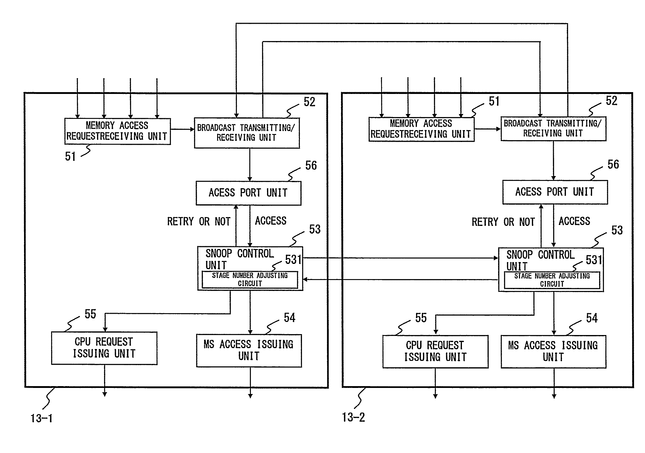
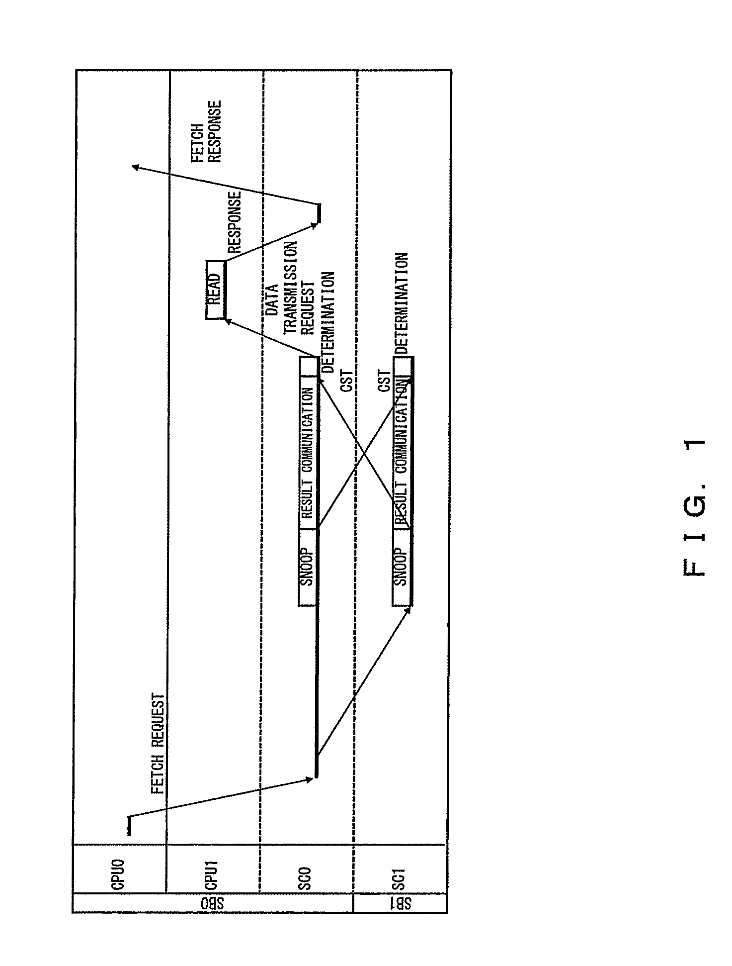
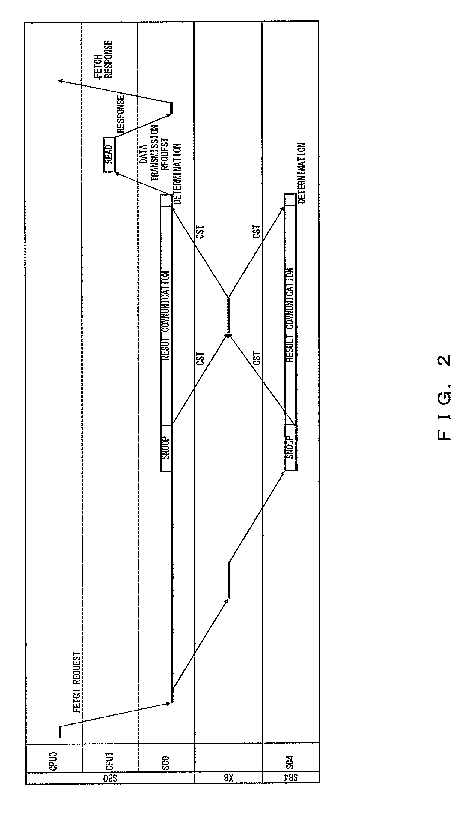
[0017]An object is to provide a system controller and a cache control method that are capable of adjusting, in a large information processing apparatus comprising multi processors, the number of stages in a snooping pipeline for snooping processes performed in a plurality of system controllers, so as to absorb differences between time required to communicate the snooping results, the differences generated depending on the size of the multi-processor system, and to determine, when there is a conflict between addresses for an access in a snooping process, a retry interval based on the number of stages in the snooping pipeline, preventing frequent occurrence of retry due to the address conflict.
[0023]The disclosed system makes it possible to absorb differences between amounts of time required to communicate snooping results, the differences generated depending on the size of the multi-processor system, and to prevent frequent occurrence of retry due to an address conflict.

Problems solved by technology

When performing cache control using MESI cache protocol described above, a fetch request (where a CPU refers to a data block stored in a cache device in another CPU) requires a write process (hereinafter referred to as “MS write”) of the data block into the main memory unit, resulting in a longer access time.
However, even the protocol utilizing the five statuses requires, when a fetch process for a system is followed by a store process for the data from another system, a status change request to switch the status of another system from O: “Shared Modified” to I: “invalid.” The store process requires longer time because of the status change request, which affects the access performance of the overall apparatus since such store process by a system on the data block acquired with a fetch request is often performed.
However, the snooping control as described above had a problem that the communication time varies according to the distances between the plurality of system controllers, requiring performance of snooping processes that are adjusted in accordance with the size of the multi-processor system.

Method used


Image

  • System controller and cache control method
  • System controller and cache control method
  • System controller and cache control method

Examples


Embodiment Construction

[0036]Hereinafter, embodiments are described, referring to the drawings.

[0037]FIG. 4 illustrates an outline of a multi-processor system.

[0038]In FIG. 4, a multi-processor system 1 comprises a plurality of system boards (2-1, 2-2). Each system board 2-1, 2-2 comprises a system controller (13-1 or 13-2), a plurality of processor modules 10-1, . . . , 10-n, a plurality of Input / Output (I / O) devices 11-1, . . . , 11-n, and a plurality of memories (MEM) 16-1, . . . , 16-n. The system boards 2-1 and 2-2 are connected to each other so that they can communicate with each other, and control read / write to / from the memories 16-1, . . . , 16-n in accordance with instructions from the processor modules 10-1, . . . , 10-n or from the I / O devices 11-1, . . . , 11-n.

[0039]FIG. 5 illustrates an outline of a large-scale multi-processor system.

[0040]In FIG. 5, a multi-processor system 3 is larger in scale than the multi-processor system 1 in FIG. 4 described above, comprising more system boards: 2-1,...


PUM


Abstract

A multiprocessor system comprises a plurality of system controllers, each of which performs a snoop processing regarding a cache device in its charge. The system controllers adjust the number of steps of a snoop pipeline for the snoop processing according to communication time with the other system controllers. The number-of-steps adjustment absorbs the difference of the communication time in the results of the snoop for each scale of the multiprocessor system. When a retrial is determined by an address conflict or the like in the snoop processing, each of the system controllers resubmits the access to be retried to the snoop pipeline after waiting until no other access which may cause an address conflict precedes. The resubmission timing prevents infinite repetition of the retrial of the snoop processing in the system controllers.

Description

CROSS REFERENCE TO RELATED APPLICATIONS[0001]This application is a continuation of PCT application of PCT / JP2006 / 303789 which was filed on Feb. 28, 2006.BACKGROUND OF THE INVENTION[0002]1. Field of the Invention[0003]The present invention relates to a system controller for controlling a cache device constituting a multi-processor system, and to a cache control method for controlling the cache device. The present invention may be applied to a system controller and a cache control method that are capable of reducing occurrence of retry due to an address conflict between accesses while snooping processes are performed.[0004]2. Description of the Related Art[0005]With increasing need for higher processing speed for computer systems, each CPU in a conventional multi-processor system has been equipped with a cache device. The cache device provided for each CPU manages its data in individual blocks, in accordance with a rule called a cache coherence protocol for maintaining the coherence a...

Claims


Application Information

Patent Timeline
Patent Type & Authority Patents(United States)
IPC IPC(8): G06F12/00
CPCG06F12/0831
Inventor SUGIZAKI, GOUNAKAGAWA, SATOSHI
Owner FUJITSU LTD
Learn More