
Level adjustment device

a level adjustment and level technology, applied in the direction of gain control, electrical transducers, transducer casings/cabinets/supports, etc., can solve the problems of acoustic signal mute, noise generation, and a lot of effort to carry out manipulation, so as to prevent the frequent occurrence of on/off switching

Active Publication Date: 2016-04-19
YAMAHA CORP
View PDF9 Cites 0 Cited by
  • Summary
  • Abstract
  • Description
  • Claims
  • Application Information

AI Technical Summary

Benefits of technology

The invention aims to enable automatic on / off switching of a pad and prevent frequent on / off switching even during fine manipulation. The level adjustment device can achieve this by automatically switching the pad, preventing interruptions during user interaction.

Problems solved by technology

Thus, there is a problem in that it takes a lot of effort to carry out the manipulation.
In general, in switching the on / off of the pad, noise is generated, the acoustic signal becomes mute.
Accordingly, there is a problem in that mute is frequently generated, and the acoustic signal is frequently discontinued, causing an undesirable state.

Method used


Image

  • Level adjustment device
  • Level adjustment device
  • Level adjustment device

Examples


first embodiment

[ FIGS. 1 to 9]

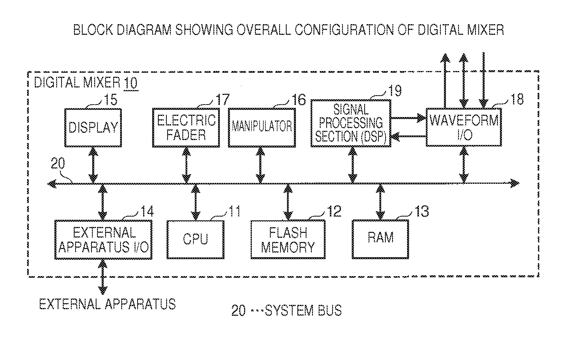
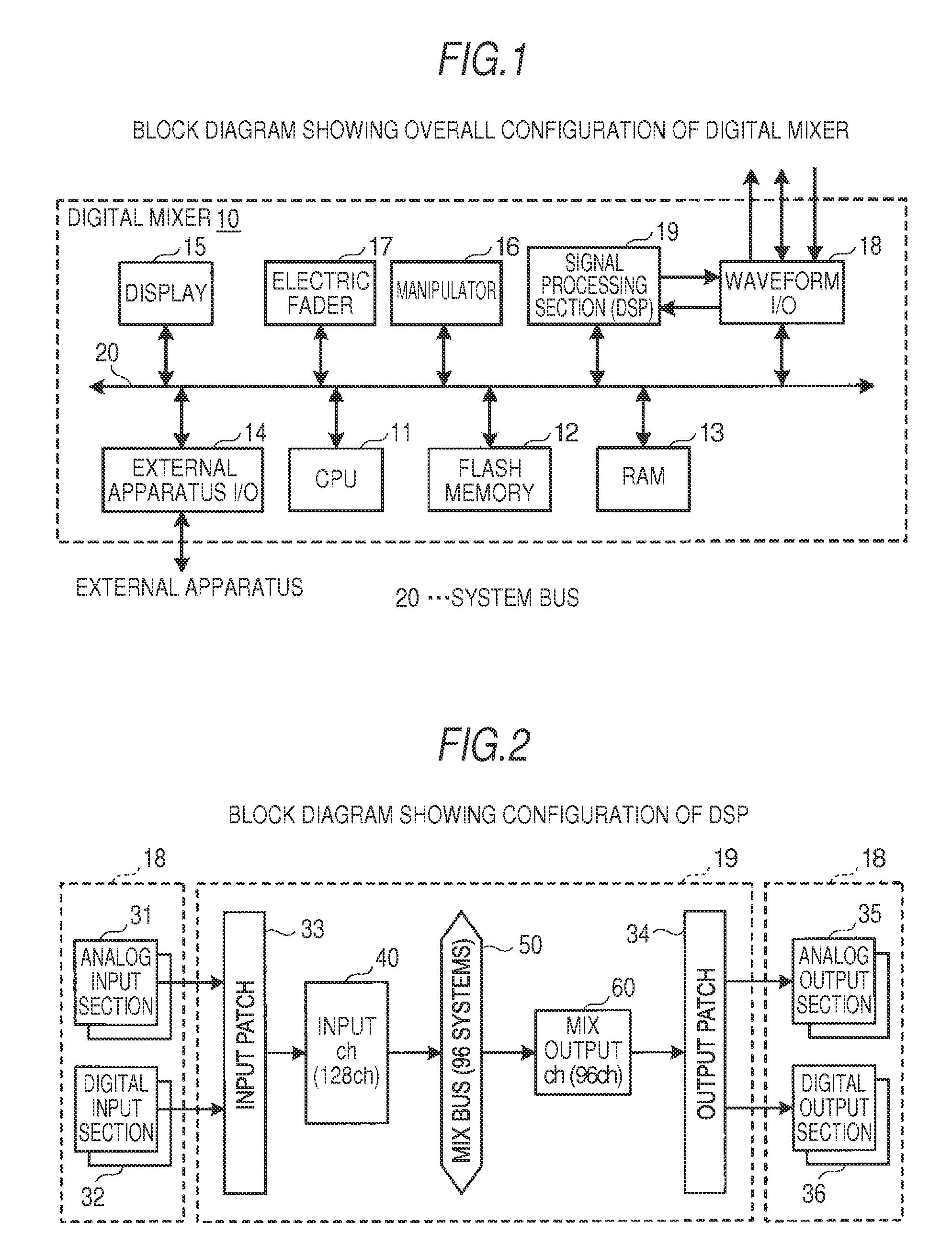
[0030]First, a digital mixer according to a first embodiment of the invention will be described. FIG. 1 is a block diagram showing the schematic hardware configuration of the digital mixer.

[0031]As shown in FIG. 1, a digital mixer 10 includes a CPU 11, a flash memory 12, a RAM 13, an external apparatus input / output section (I / O) 14, a display 15, a manipulator 16, an electric fader 17, a waveform I / O 18, and a signal processing section (DSP) 19, which are connected to each other through a system bus 20. The digital mixer operates as an acoustic signal processing apparatus which has a function of performing signal processing, such as mixing or equalizing, for a plurality of input acoustic signals and outputting the acoustic signal after the signal processing. The digital mixer also has a function as a level adjustment device which adjusts the level of the input analog acoustic signal. In this specification, the term “level” means the amplitude level of the acoustic sig...

second embodiment

[ FIGS. 10 to 13]

[0096]Next, a second embodiment of the invention will be described. The second embodiment is characterized in that a single pad on / off switching point is provided and, when the performance mode starts, the switching point is moved so as to be away from the level adjustment value. In a digital mixer 10 of the second embodiment, the configuration shown in FIGS. 1 to 4 including the hardware configuration and the like is the same as the digital mixer 10 of the above-described first embodiment, thus description thereof will be omitted.

[0097]The condition for switching the on / off of the pad in the second embodiment will be described with reference to FIG. 10.

[0098]The digital mixer 10 has a single switching point at which the on / off of the pad is switched. That is, a switching point Tsw is used which is common to the pad-on state and the pad-off state. In the pad-off state, when the level adjustment value is changed and reaches Tsw, pad-off is switched to pad-on. In the ...


PUM


Abstract

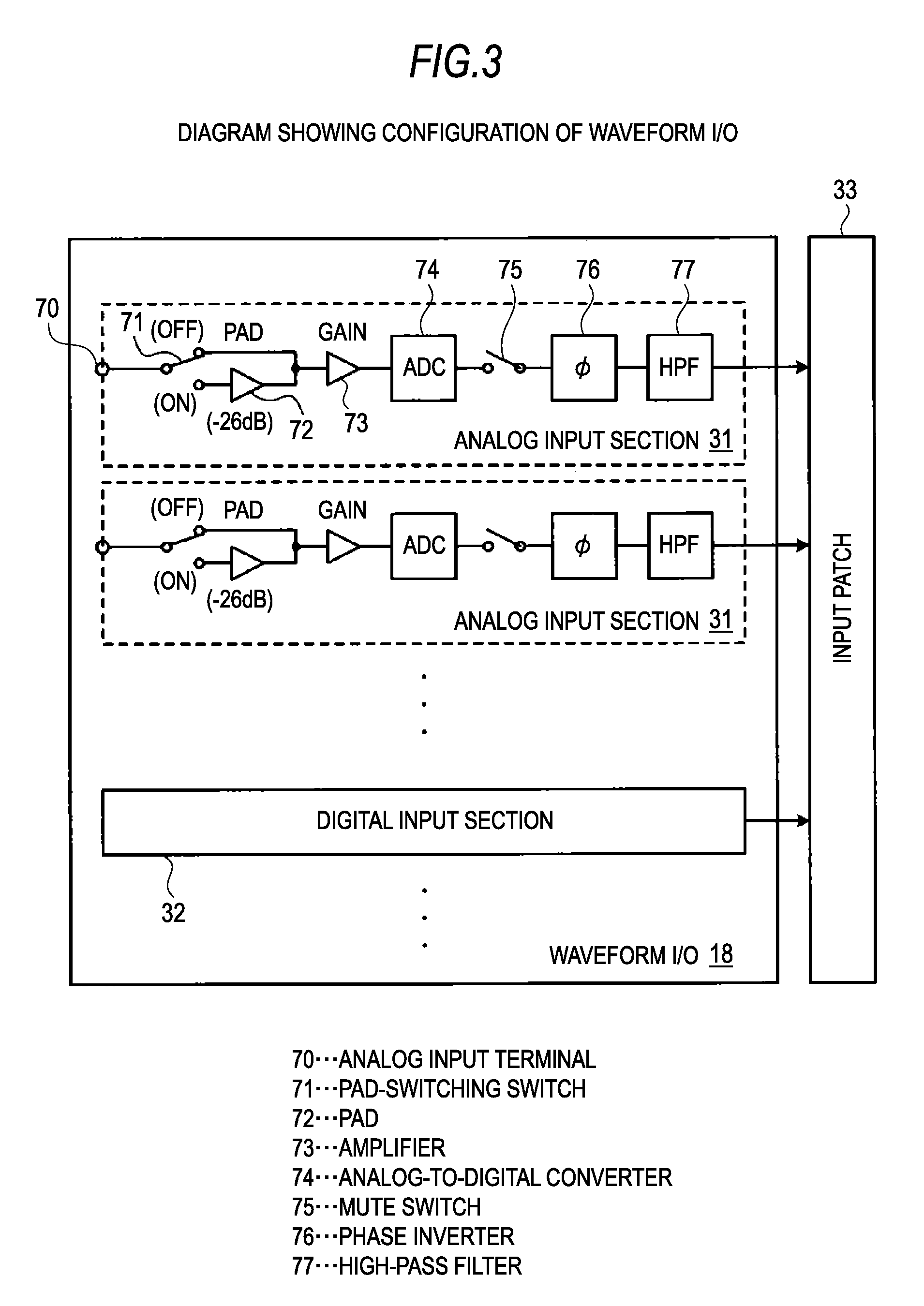
It is possible to enable automatic on / off switching of a pad and to prevent frequent occurrence of on / off switching of a pad even when a user carries out fine manipulation. A level adjustment device includes a pad which attenuates a signal by a predetermined level, an amplifier which is provided at the back of the pad to adjust the level of the signal with a variable amplification rate or attenuation rate, and a level adjustment unit which, when the pad is off, uses only the amplifier and, when the pad is on, uses the amplifier and the pad to adjust the level of the acoustic signal. The setting of a level adjustment value by the level adjustment unit is received, when the level adjustment value reaches a predetermined switching point Tsw, the on / off of the pad is switched, and when an instruction is issued to start a performance mode, the value of the switching point Tsw is changed so as to be away from the level adjustment value at the point of time of the instruction.

Description

BACKGROUND OF THE INVENTION[0001]1. Field of the Invention[0002]The present invention relates to a level adjustment device which adjusts the level of an acoustic signal and, in particular, to a level adjustment device which is suitable for level adjustment when an analog acoustic signal is input to an acoustic signal processing apparatus, such as a digital mixer.[0003]2. Background Art[0004]In an acoustic signal processing apparatus, such as a digital mixer, an amplifier is provided in an input section of an analog acoustic signal to adjust the gain. The amplifier is configured to adjust the level of an input analog acoustic signal in accordance with a manipulation of a user.[0005]The reason for the adjustment is that an acoustic signal input from an analog input terminal has various amplitude levels depending on what type of apparatus is used as a generation source, and the level balance of the acoustic signal is arranged such that all the amplitude levels are optimally handled in ...

Claims


Application Information

Patent Timeline
Patent Type & Authority Patents(United States)
IPC IPC(8): H03G3/00H03G3/30H03G1/00H03G3/02H03F1/02
CPCH03G3/3026H03G1/0088H03G3/02H03G3/301H03F1/0261H03F2203/7203
Inventor AISO, MASARU
Owner YAMAHA CORP
Learn More