Compliant expansion swage

a technology of expansion swage and tubular swage, which is applied in the direction of drilling casings, drilling pipes, and accessories for wellbores/wells, etc., can solve the problems of fixed diameter cones that cannot be flexible in the radially inward direction to allow for variations in internal diameter of casings, fixed diameter cones that cannot be withdrawn from wellbores, and time-consuming and costly problems

Active Publication Date: 2011-07-19
WEATHERFORD TECH HLDG LLC
View PDF67 Cites 9 Cited by
  • Summary
  • Abstract
  • Description
  • Claims
  • Application Information

AI Technical Summary

Problems solved by technology

However, the fixed diameter cone provides no flexibility in the radially inward direction to allow for variations in the internal diameter of the casing.
This variation in the internal diameter of the casing can cause the fixed diameter cone to become stuck in the wellbore, if the variation is on the low side.
A stuck fixed diameter cone creates a major, time consuming and costly problem that can necessitate a sidetrack of the wellbore since the solid cone cannot be retrieved from the well and the cone is too hard to mill up.
Further, this variation in the internal diameter of the casing can also cause an inadequate expansion of the tubular in the casing if the variation is on the high side, which may result in an inadequate coupling between the tubular and the casing.

Method used


Image

  • Compliant expansion swage
  • Compliant expansion swage
  • Compliant expansion swage

Examples


Embodiment Construction

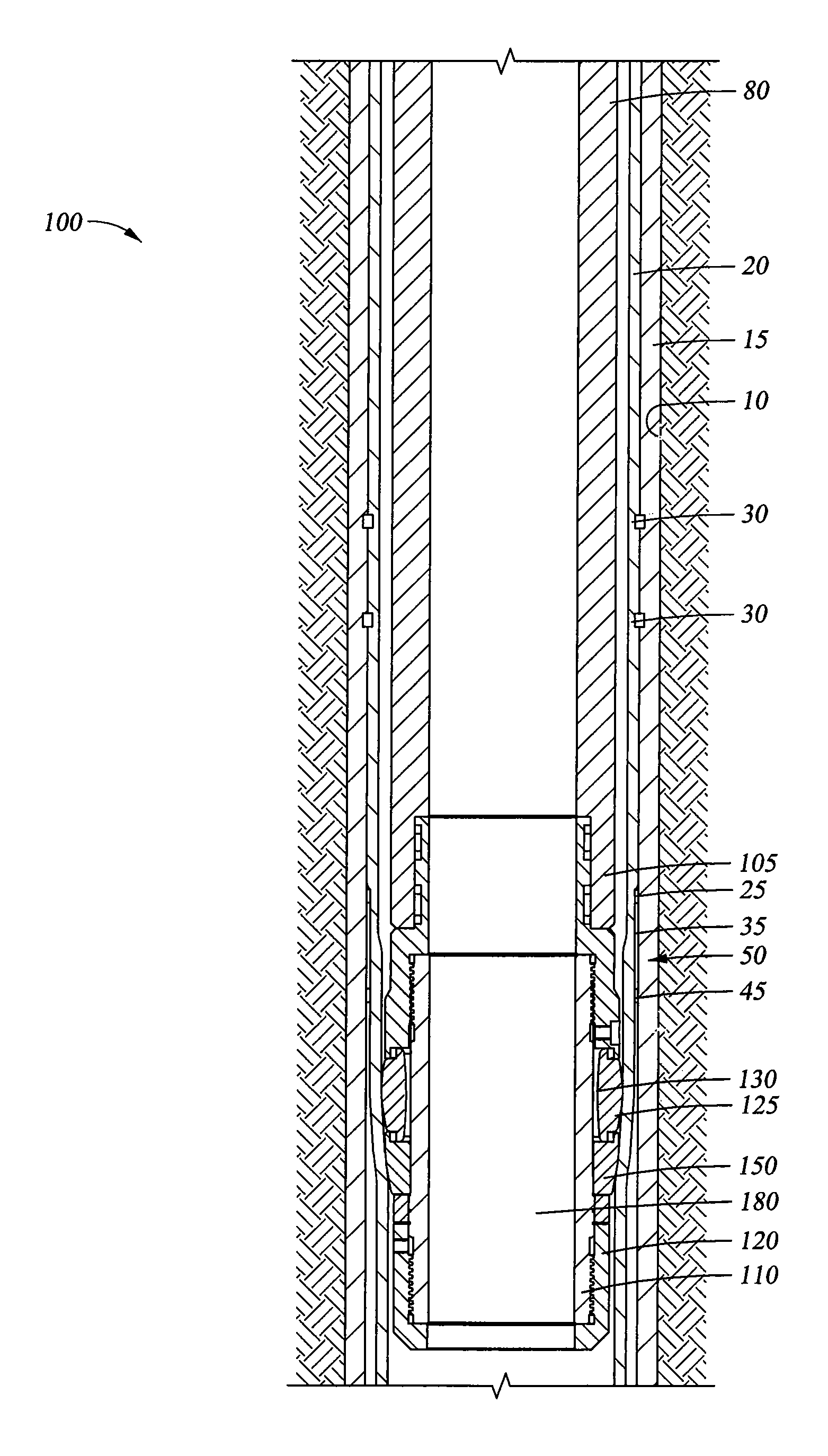
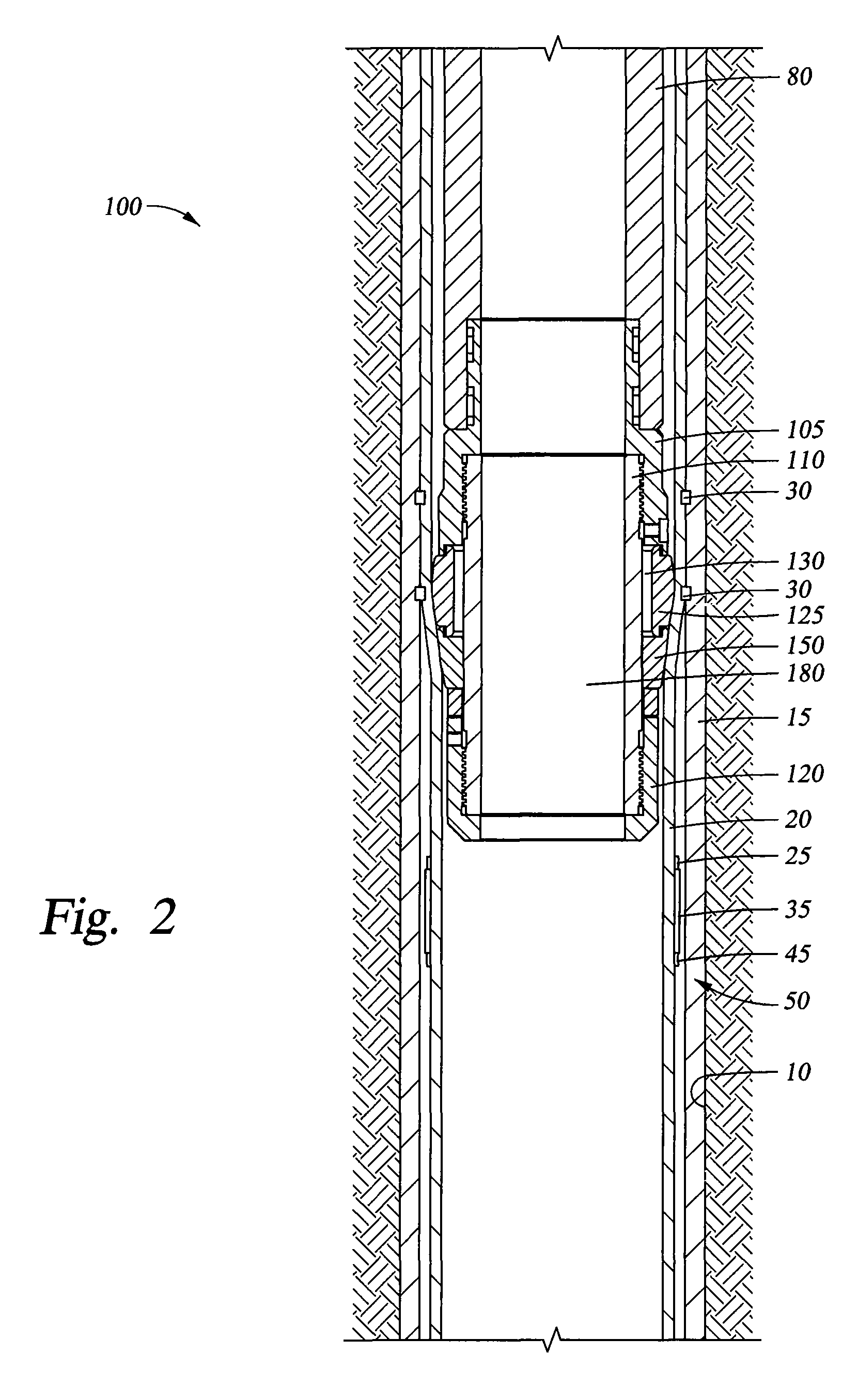
[0032]Embodiments of the invention generally relate to a swage assembly having a cone portion capable of deflecting in response to a restriction or obstruction encountered while expanding a tubular. While in the following description the tubular is illustrated as a liner, the tubular can be any type of downhole tubular. For example, the tubular may be an open-hole patch, a cased-hole patch or an expandable sand screen. To better understand the aspects of the swage assembly of the present invention and the methods of use thereof, reference is hereafter made to the accompanying drawings.

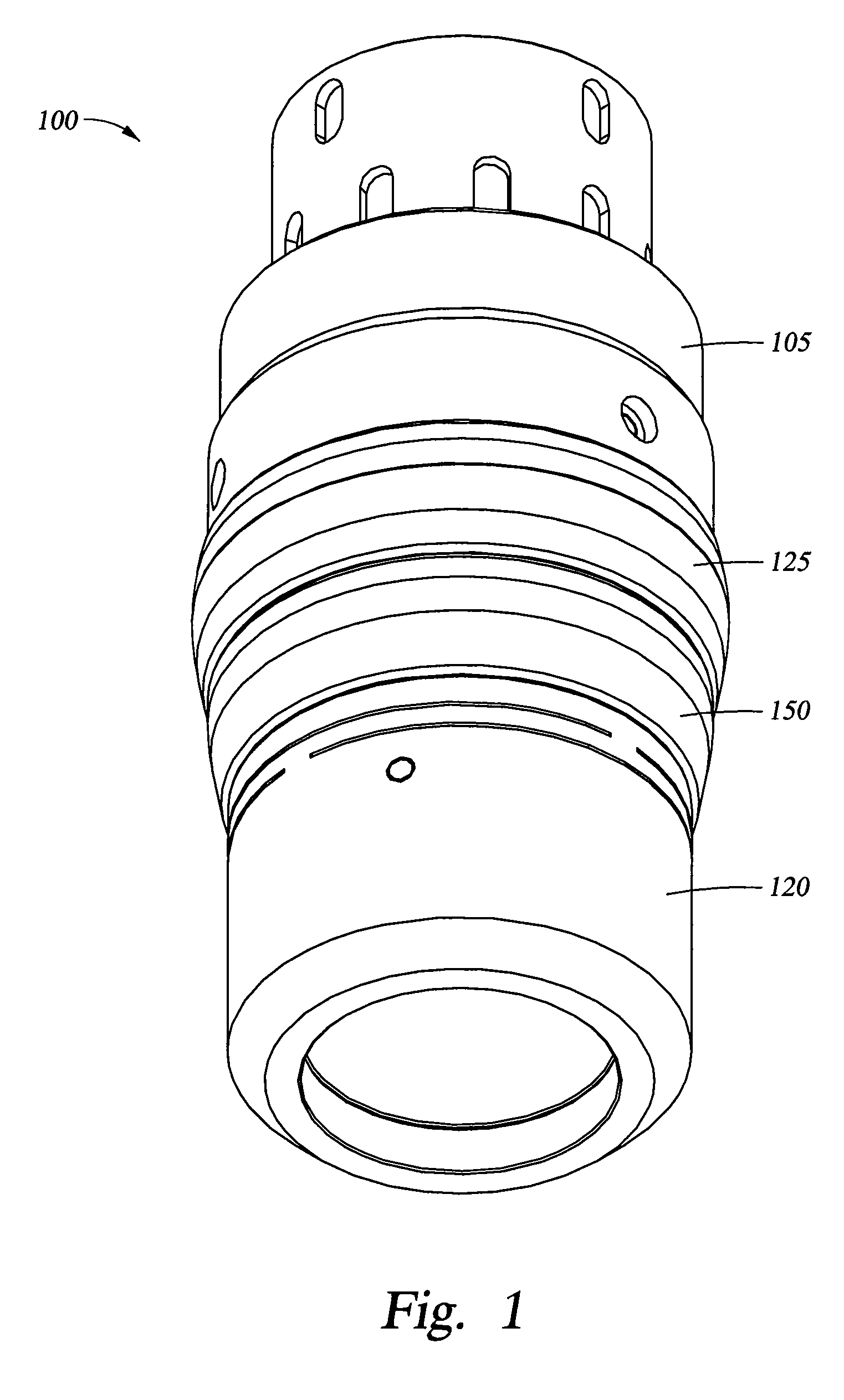
[0033]FIG. 1 is an isometric view of a swage assembly 100 according to one embodiment of the invention. The swage assembly 100 is configured to expand a tubular in the wellbore. The swage assembly 100 generally includes a substantially solid deformable cone 125. As will be described herein, the swage assembly 100 may be moved from a first configuration where the swage assembly 100 has a substantially c...


PUM

PropertyMeasurementUnit
plastic deformationaaaaaaaaaa
yield strengthaaaaaaaaaa
diameteraaaaaaaaaa

Abstract

The present invention generally relates to a swage assembly that is movable from a compliant configuration having a first shape to a substantially non-compliant configuration having a second shape. In one aspect, an expansion swage for expanding a wellbore tubular is provided. The expansion swage includes a body and a solid cone disposed on the body. The expansion swage further includes a deformable cone disposed on the body, wherein the solid cone is made from a first material and the deformable cone is made from a second material and wherein the deformable cone is movable relative to the body when the expansion swage is in a compliant configuration. In another aspect, a method of expanding a wellbore tubular is provided.

Description

BACKGROUND OF THE INVENTION[0001]1. Field of the Invention[0002]Embodiments of the invention generally relate to apparatus and methods for expanding a tubular in a wellbore. More particularly, embodiments of the invention relate to a compliant expansion swage.[0003]2. Description of the Related Art[0004]Hydrocarbon wells are typically initially formed by drilling a borehole from the earth's surface through subterranean formations to a selected depth in order to intersect one or more hydrocarbon bearing formations. Steel casing lines the borehole, and an annular area between the casing and the borehole is filled with cement to further support and form the wellbore. Several known procedures during completion of the wellbore utilize some type of tubular that is expanded downhole, in situ. For example, a tubular can hang from a string of casing by expanding a portion of the tubular into frictional contact with a lower portion of the casing therearound. Additional applications for the ex...

Claims


Application Information

Patent Timeline
Patent Type & Authority Patents(United States)
IPC IPC(8): E21B43/10
CPCE21B43/105B21D31/04
Inventor RING, LEVGANDIKOTA, VARADARAJULUKE, MIKE A.LI, DAVID S.
Owner WEATHERFORD TECH HLDG LLC
Why Eureka
Try Eureka