Illuminating caster

a technology of illuminating casters and casters, which is applied in the direction of lighting and heating apparatus, semiconductor devices of light sources, and support devices for lighting, etc., can solve the problems of slacking or breaking, easy cold failure of illuminating casters after some time of use, etc., and achieve the effect of reliable illuminating casters

Inactive Publication Date: 2011-07-19
HU AN MIN
View PDF5 Cites 17 Cited by
  • Summary
  • Abstract
  • Description
  • Claims
  • Application Information

AI Technical Summary

Benefits of technology

[0008]It is the primary objective of the present invention to provide a buggy, a walker, a toy, a sports gear, a wheeled chair or a trolley with a reliable illuminating caster.

Problems solved by technology

The illuminating casters cold easily fail to illuminate after some time of use.
The failure could be attributed to slacking of the elements relative to one another or breaking of some of the elements.
The slacking or breaking could be attributed to vibration during the use of the roller skaters.

Method used


Image

  • Illuminating caster
  • Illuminating caster
  • Illuminating caster

Examples


Embodiment Construction

[0017]Referring to FIG. 4, there is shown an illuminating caster according to a first embodiment of the present invention.

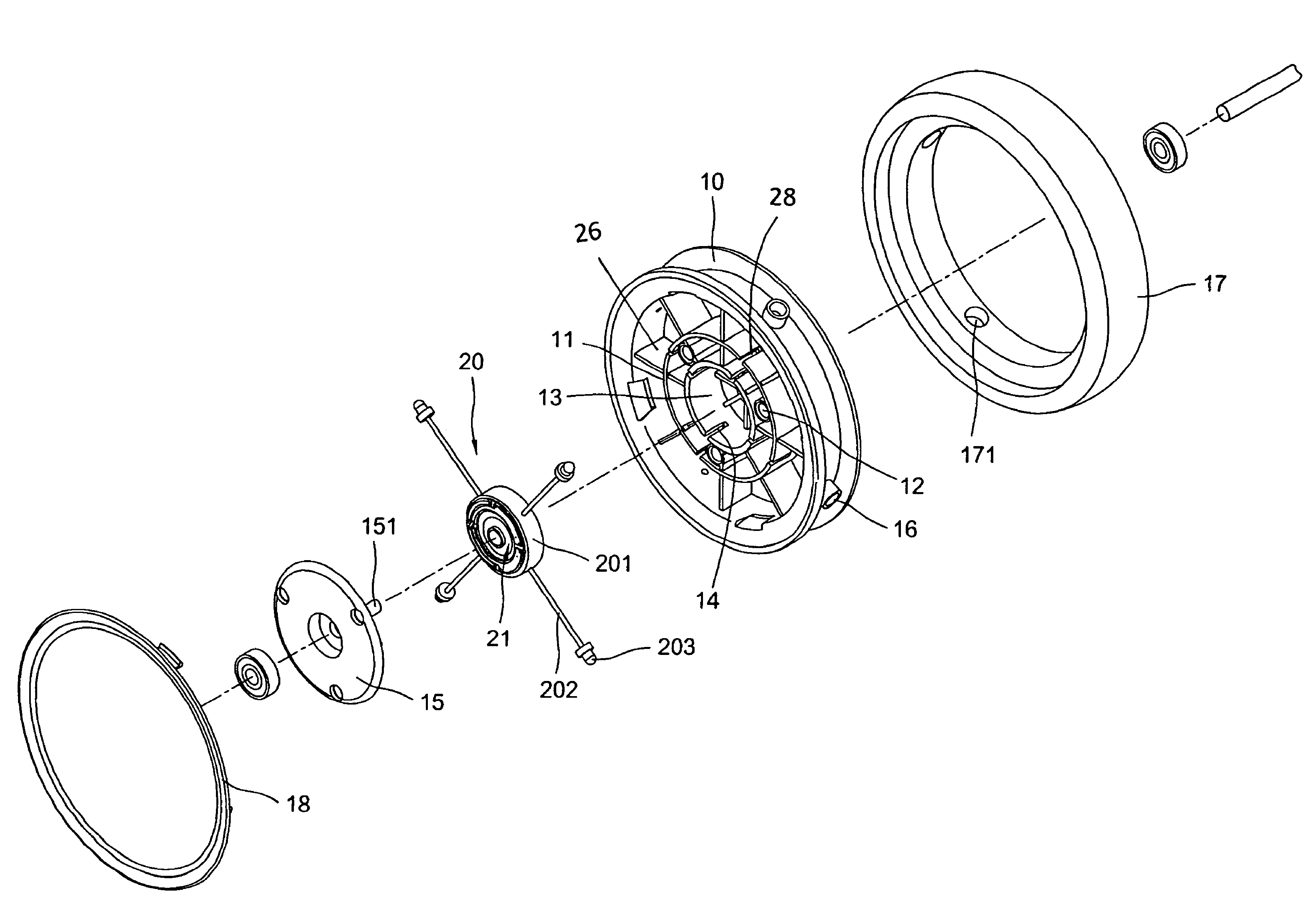
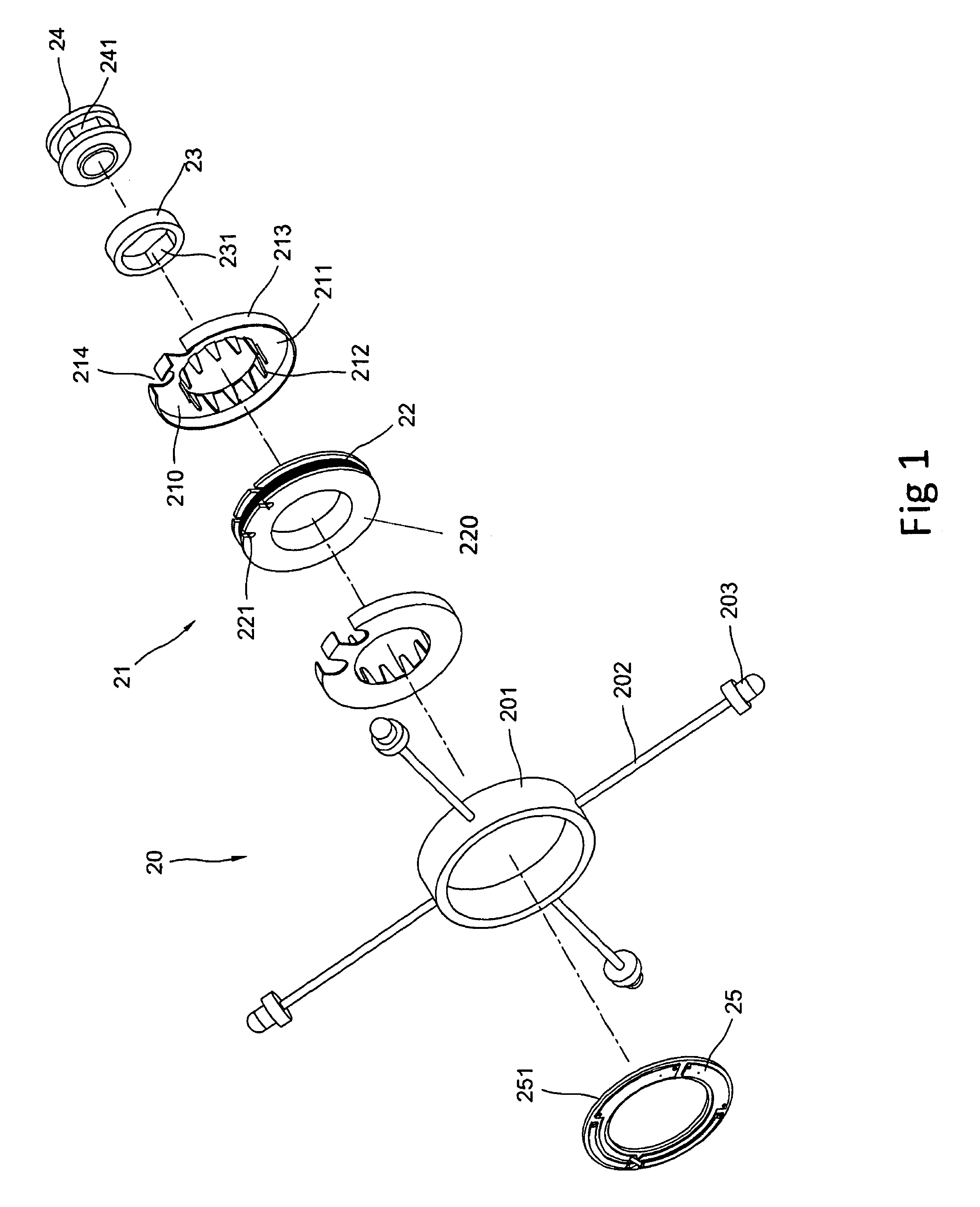
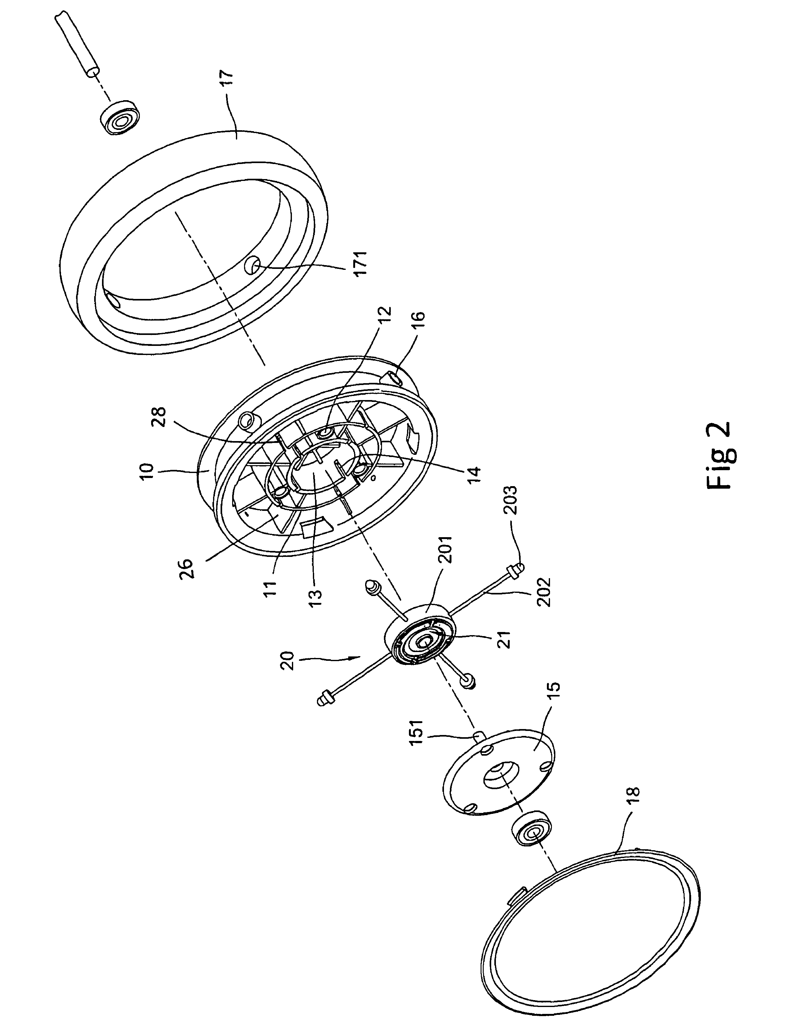
[0018]Referring to FIGS. 2 and 3, the illuminating caster includes a rim 10, a tire 17 provided on the rim 10, illuminating elements 203 disposed in the tire 17 and a generator 20 disposed in the rim 10 and used to energize the illuminating elements 203. Spokes 26 are extended to the rim 10 from a hub 13. An annular rib 11 is formed between the rim 10 and the hub 13. Slits 28 are defined in the annular rib 11. The spokes 26 intersect with the annular rib 11. Slits 14 are defined in the hub 13. Cylinders 12 are formed around the hub 13. Apertures 16 are defined in the rim 10.

[0019]The tire 17 is made of a transparent or translucent material so that light emitted from the illuminating elements 203 can be seen through the tire 17. The tire 17 includes cavities 171 defined in an internal side thereof. The illuminating elements 203 are disposed in the cavities 171.

[00...


PUM


Abstract

An illuminating caster includes an at least translucent tire, a rim for supporting the wheel, a hub including slits defined therein, spokes extending to the rim from the hub, illuminating elements located in the vicinity of the tire and a generator. The generator includes a ring disposed in the hub, rods each extending to a related one of the illuminating elements from the ring through a related one of the slits, a circuit board disposed in the ring and connected to the illuminating elements, an annular shell disposed in the ring, a coil disposed in the annular shell and connected to the circuit board, a permanent magnet disposed in but separated from the coil and a lining provided between the permanent magnet and an axle.

Description

BACKGROUND OF THE INVENTION[0001]1. Field of the Invention[0002]The present invention relates to an illuminating caster for a buggy, a walker, a toy, a sports gear, a wheeled chair or a trolley and, more particularly, to a reliable illuminating caster.[0003]2. Related Prior Art[0004]A buggy, a walker, a toy, a sports gear, a wheeled chair or a trolley needs casters. Conventional casters are plain.[0005]Some roller skaters are equipped with illuminating casters for decorative and signaling purposes. An illuminating caster includes illuminating elements and a small generator for energizing the illuminating elements. The small generator includes a coil, a permanent magnet and a circuit board. When the illuminating caster is rotated, there is relative rotation between the coil and the permanent magnet. Thus, electricity is generated to energize the illuminating elements.[0006]The illuminating casters cold easily fail to illuminate after some time of use. The failure could be attributed ...

Claims


Application Information

Patent Timeline
Patent Type & Authority Patents(United States)
IPC IPC(8): B60Q1/26
CPCA63C17/223A63H17/262A63H17/28A63H33/22B62B9/005F21V33/008A61G5/10A63C2203/14F21L13/06F21Y2101/02F21Y2115/10
Inventor HU, AN-MIN
Owner HU AN MIN
Why Eureka
Try Eureka