Opto-electric hybrid module and manufacturing method thereof

a hybrid module and opto-electric technology, applied in the direction of optical elements, circuit optical details, instruments, etc., can solve the problems of increasing reducing accuracy, so as to reduce the propagation loss of light beams, reduce the distance between the distal end surface of the extension of the core and the optical element, and improve the reliability of light propagation

Active Publication Date: 2009-12-03
NITTO DENKO CORP
View PDF6 Cites 21 Cited by
  • Summary
  • Abstract
  • Description
  • Claims
  • Application Information

AI Technical Summary

Benefits of technology

[0010]In view of the foregoing, it is an object of the present invention to provide an opto-electric hybrid module capable of reducing the propagation loss of light beams, and a manufacturing method thereof.
[0013]In the opto-electric hybrid module according to the present invention, the portion of the core near the end portion thereof extends from the reflection portion toward the optical element, and the extension is positioned in the through hole for light propagation. The distal end surface of the extension is in face-to-face relationship with the light-receiving and light-emitting portion of the above-mentioned optical element. Thus, the distance between the distal end surface of the extension of the core and the optical element is shortened. For example, when the above-mentioned optical element is a light-emitting element, this allows light beams emitted from the light-emitting portion of the above-mentioned light-emitting element to enter the distal end surface of the extension of the above-mentioned core before the light beams are diffused too widely. Further, the light beams are guided through the interior of the extension of the above-mentioned core to the reflection portion of the core with reliability. Then, the light beams are reflected from the above-mentioned reflection portion to travel further into the depth of the core. Similarly, when the light beams exit from the distal end surface of the extension of the above-mentioned core (or when the above-mentioned optical element is a light-receiving element), the light beams traveling from the depth of the core to the reflection portion of the core are reflected from the reflection portion, and thereafter are guided through the interior of the extension of the above-mentioned core to the distal end surface thereof with reliability. Then, the light-receiving portion of the light-receiving element can receive the light beams exiting from the distal end surface thereof before the light beams are diffused too widely. In this manner, the opto-electric hybrid module according to the present invention, in which the reliability of the light propagation is improved, is capable of reducing the propagation loss of the light beams.

Problems solved by technology

For these reasons, there is a problem with the prior art opto-electric hybrid module in that the propagation loss of the light beams L is increased.
As a result, this decreases the accuracy of alignment (positioning) of the light-emitting element 11 and the like with (relative to) the optical path conversion mirrors 87a provided in the opposite end portions of the core 87 to result in the increase in the propagation loss of the light beams L.

Method used


Image

  • Opto-electric hybrid module and manufacturing method thereof
  • Opto-electric hybrid module and manufacturing method thereof
  • Opto-electric hybrid module and manufacturing method thereof

Examples


Embodiment Construction

[0024]Next, embodiments according to the present invention will now be described in detail with reference to the drawings.

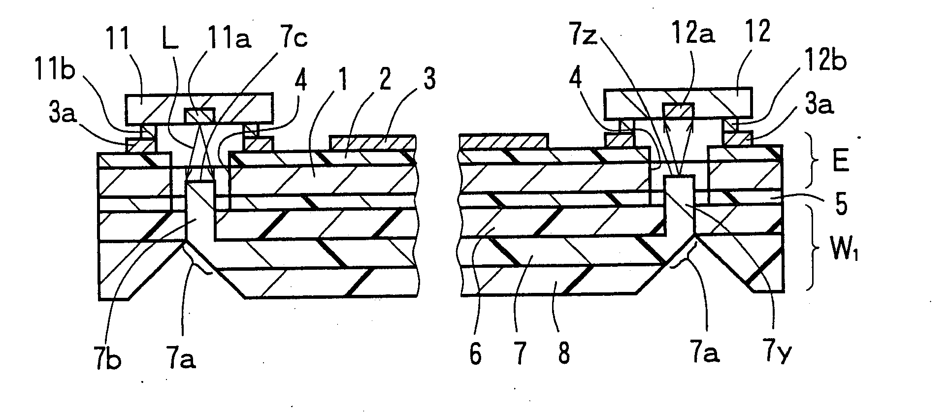
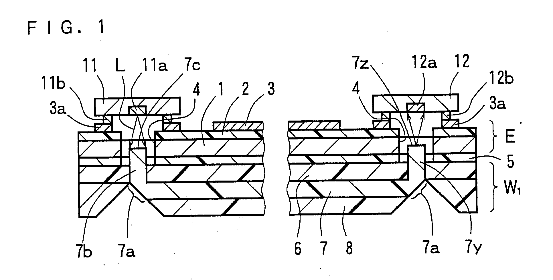
[0025]FIG. 1 shows an opto-electric hybrid module according to a first embodiment of the present invention. This opto-electric hybrid module includes: an electric circuit board E with an electric circuit 3 formed on the surface thereof; a light-emitting element 11 and a light-receiving element 12 both mounted on a first surface of the electric circuit board E on which the electric circuit 3 is formed; and an optical waveguide W1 bonded with an adhesive 5 to a second surface (or a back surface) of the above-mentioned electric circuit board E opposite from the first surface (or a front surface). The above-mentioned optical waveguide W1 is constructed such that an under cladding layer 6, a core 7, and an over cladding layer 8 are formed in the order named from the back surface side of the above-mentioned electric circuit board E. V-shaped notches are formed in porti...


PUM

PropertyMeasurementUnit
thicknessaaaaaaaaaa
thicknessaaaaaaaaaa
thicknessaaaaaaaaaa

Abstract

An opto-electric hybrid module capable of reducing the propagation loss of light beams, and a manufacturing method thereof. An opto-electric hybrid module in which a light-emitting element and a light-receiving element are mounted on the front surface side of an electric circuit board E, and an optical waveguide W1 is bonded to the back surface side thereof. The optical waveguide W1 includes a core having opposite end portions formed as light reflection portions. Portions of the core near the opposite end portions are formed as extensions extending from the light reflection portions toward the light-emitting element and the light-receiving element. The extensions and are positioned in through holes for light propagation formed in the electric circuit board E, and have distal end surfaces and in face-to-face relationship with a light-emitting portion of the light-emitting element and a light-receiving portion of the light-receiving element, respectively.

Description

RELATED APPLICATIONS[0001]This application claims the benefit of U.S. Provisional Application No. 61 / 060,920, filed Jun. 12, 2008, which is hereby incorporated by reference.BACKGROUND OF THE INVENTION[0002]1. Field of the Invention[0003]The present invention relates to an opto-electric hybrid module in which an optical waveguide and an electric circuit with an optical element mounted thereon are combined, and to a manufacturing method thereof.[0004]2. Description of the Related Art[0005]An opto-electric hybrid module is manufactured, for example, as shown in FIG. 9, by preparing an electric circuit board E and an optical waveguide W0 individually, bonding both to each other with an adhesive 5, and then mounting a light-emitting element 11 and a light-receiving element 12 on portions of the above-mentioned electric circuit board E corresponding to opposite end portions of the above-mentioned optical waveguide W0 (see, for example, Japanese Patent Application Laid-Open No. 2004-302345...

Claims


Application Information

Patent Timeline
Patent Type & Authority Applications(United States)
IPC IPC(8): G02B6/12B29C65/00G02B6/122G02B6/13G02B6/42H01L33/48
CPCG02B6/4214Y10T156/1089H05K1/0274G02B6/43H01L2224/16225G02B6/12G02B6/42
Inventor HODONO, MASAYUKI
Owner NITTO DENKO CORP
Why Eureka
Try Eureka