Photonic bandgap fiber

a bandgap fiber and bandgap technology, applied in the field of photonic bandgap fibers, can solve the problems of amplifying spontaneous emission, amplifying fibers and light-guiding fibers, and stimulating raman scattering, etc., to suppress the generation of stimulated raman scattering, suppress the loss of pumping light, and reduce the loss of ligh

Active Publication Date: 2009-08-20
THE FUJIKURA CABLE WORKS LTD
View PDF10 Cites 12 Cited by
  • Summary
  • Abstract
  • Description
  • Claims
  • Application Information

AI Technical Summary

Benefits of technology

[0019]In the exemplary embodiments of the present invention, the high refractive index portions form a periodic structure due to the photonic bandgap effect, and a wavelength filter effect occurs not only at a specified wavelength, but over a certain wavelength range. Accordingly, it is possible to provide a fiber that is effective for suppressing the propagation of light with a wavelength range spreading to some extent, by suppressing stimulated Raman scattering and spontaneous emission.
[0035]Also, in exemplary embodiments of the present invention, by forming the glass portion entirely with a silica glass material, it is possible to reduce propagation loss.

Problems solved by technology

However, as the output power of fiber lasers has increased, two problems have become evident.
The first problem is stimulated Raman scattering.
This is a problem in both the amplifying fiber and the light-guiding fiber.
One more problem is the amplified spontaneous emission.
This is a problem in the amplifying fiber.
However, there are the following problems in the conventional art.
In the fiber that is disclosed in the Suppression of Raman Gain publication, since the cut-off wavelength of the fundamental mode exists at a wavelength that is longer than the wavelength of the signal light, it is not possible to suppress spontaneous emission on the shorter wavelength side than the wavelength of the signal light.
In the fiber that is disclosed in the Suppression of Stimulated Raman Scattering publication, since the coupling to the mode guided through the ring exists at many wavelengths, even the signal light may be suppressed due to manufacturing variations, so that manufacturing is difficult or the tolerance with respect to manufacturing variations is low.
Also, since the coupling to the mode that is guided through the ring exists at a comparatively narrow band of approximately 10 nm to 30 nm, it is difficult to accurately match the band to the wavelengths that need to be suppressed in terms of manufacturing, and a band of Raman scattering cannot be entirely covered, and suppression of the spontaneous emission can only be performed in a restricted band.

Method used


Image

  • Photonic bandgap fiber
  • Photonic bandgap fiber
  • Photonic bandgap fiber

Examples


exemplary embodiment 1

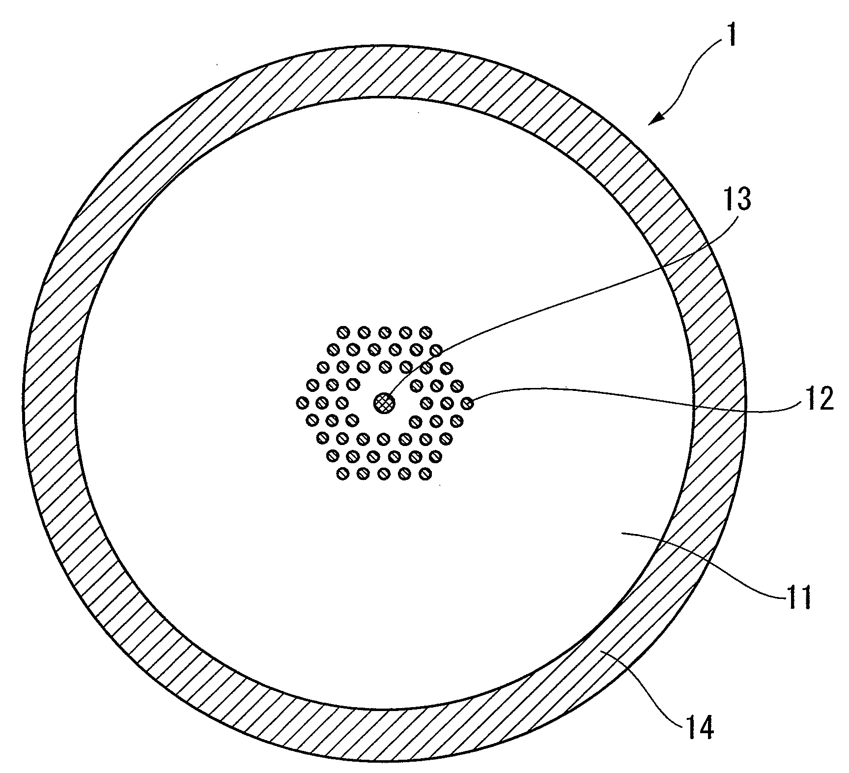
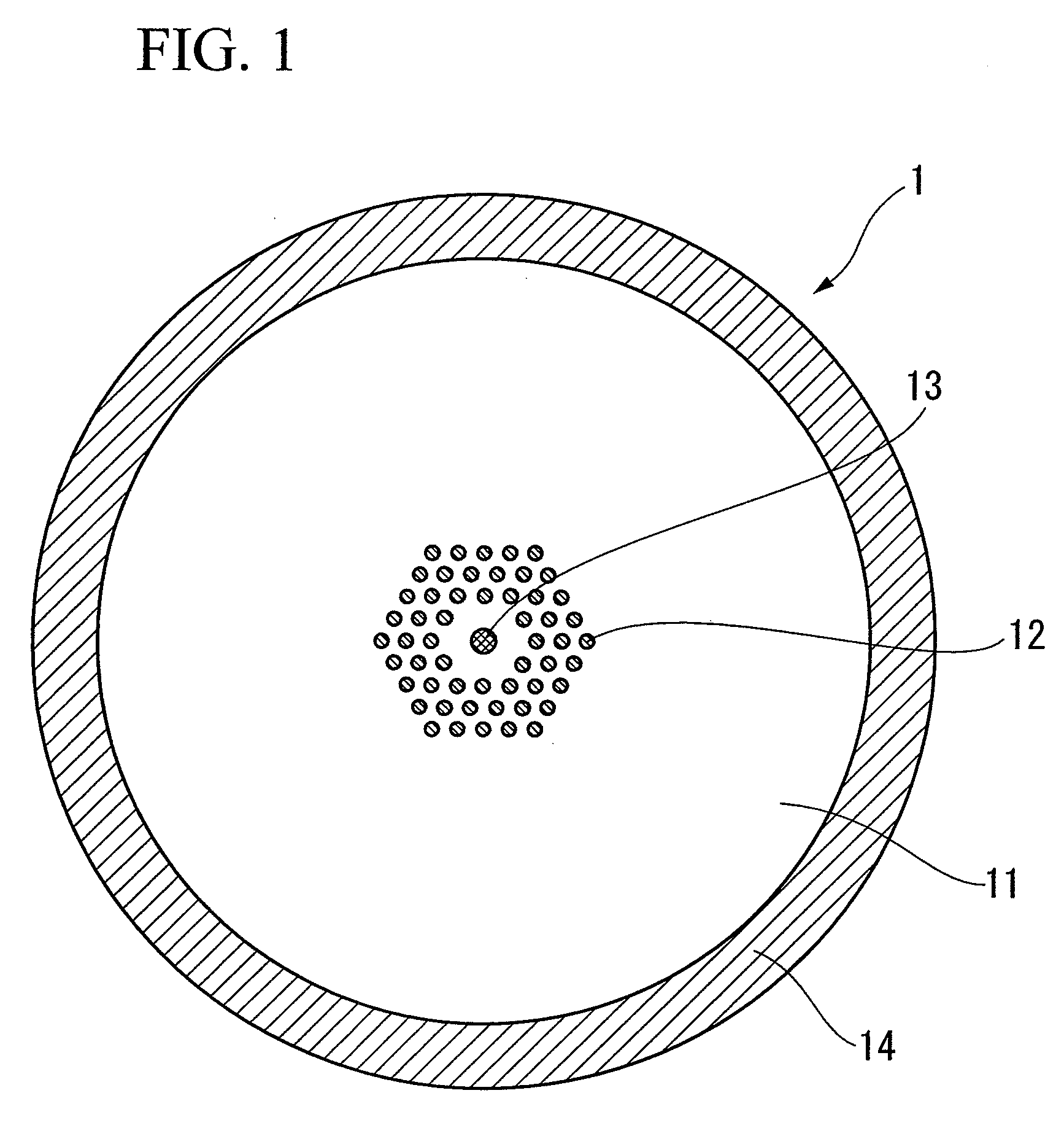
[0059]FIG. 1 is a cross-sectional view that shows the structure of a light-guiding fiber of In light-guiding fiber 1, high refractive index portions 12, which are made of germanium dioxide doped silica glass and have a relative refractive-index difference of 2.8% with respect to pure silica glass, are provided in a first cladding 11 made of pure silica glass with a triangular lattice structure that forms a periodic photonic band.

[0060]The photonic band has a layered structure circumferentially centered around a first core 13, having a relative refractive-index difference of 0.3% with respect to pure silica glass, where each layer comprises a ring of adjacent high index refraction portions together forming a lattice structure with a lattice constant Λ. A spacing equivalent to the size of a layer including six high refractive index portions resides between the core 13 and the innermost high refractive index portions of the lattice structure. For example, such a lattice structure can ...

exemplary embodiment 2

[0076]FIG. 4 is a cross-sectional view that shows the structure of an amplifying fiber 2 of exemplary Embodiment 2 according to the present invention.

[0077]In the amplifying fiber 2, high refractive index portions 22 which are made of germanium dioxide doped silica glass, and have a relative refractive-index difference of 2.5% with respect to pure silica glass, are provided in a first cladding 21 made of pure silica glass with a triangular lattice periodic structure to form a photonic band. Similarly to Embodiment 1, the triangular lattice structure has a layered structure circumferentially centered around a core 23, which functions as an amplification medium by doping ytterbium oxide in pure silica glass and has a relative refractive-index difference of 0.3% with respect to pure silica glass, where each layer comprises a ring of adjacent high index refraction portions together forming a lattice structure with a lattice constant Λ. A spacing equivalent to the size of a layer includi...

exemplary embodiment 3

[0084]FIG. 7 is a cross-sectional view that shows the structure of a fiber 3 of exemplary Embodiment 3 according to the present invention.

[0085]In the fiber 3, high refractive index portions 32 which are made of germanium dioxide doped silica glass, and have a relative refractive-index difference of 2.0% with respect to pure silica glass, are provided in a first cladding 31 made of pure silica glass with a triangular lattice periodic structure to form a photonic band. Similarly to Embodiment 1, the triangular lattice structure has a layered structure circumferentially centered around a core 33, having a relative refractive-index difference of 0.7% with respect to pure silica glass, where each layer comprises a ring of adjacent high index refraction portions together forming a lattice structure with a lattice constant Λ. A spacing equivalent to the size of a layer including six high refractive index portions resides between the core 33 and the innermost high refractive index portions...


PUM

PropertyMeasurementUnit
wavelengthaaaaaaaaaa
wavelengthsaaaaaaaaaa
wavelengthaaaaaaaaaa

Abstract

A photonic bandgap fiber includes a core and a cladding that surrounds the core. In this photonic bandgap fiber, high refractive index portions which have a refractive index higher than that of a medium of the cladding are provided in the cladding so as to form a triangular lattice structure with a lattice constant Λ, and the refractive index of the core is higher than the refractive index of the medium of the cladding and lower than the refractive index of the high refractive index portion. The coupling length between the core and the high refractive index portion that is closest to the core is longer than the coupling length between adjacent high refractive index portions, or a periodic structure formed by the high refractive index portions is not provided around the entirely of the area along the circumference of the core.

Description

[0001]This Application claims priority from Japanese Patent Application No. 2006-297522, filed Nov. 1, 2006, and Japanese Patent Application No. 2007-111552, filed Apr. 20, 2007, the contents of which are incorporated herein by reference.TECHNICAL FIELD[0002]Exemplary embodiments of the present invention relate to a photonic bandgap fiber, in particular, to a photonic bandgap fiber that enhances the performance of suppressing stimulated Raman scattering and amplified spontaneous emission generated in an optical fiber.BACKGROUND ART[0003]In recent years, high-power optical amplifiers (fiber lasers, fiber amplifiers) using a rare-earth doped optical fiber have received attention. Among these, since high-power fiber lasers have the characteristics of being easily cooled and offering high beam quality compared to solid-state lasers, they are attracting a great amount of attention particularly in the field of laser machining. In a high-power fiber laser, a pumping light and a signal ligh...

Claims


Application Information

Patent Timeline
Patent Type & Authority Applications(United States)
IPC IPC(8): H01S3/00G02B6/02
CPCG02B6/02347H01S3/06708G02B6/02357
Inventor GOTO, RYUICHIRO
Owner THE FUJIKURA CABLE WORKS LTD
Why Eureka
Try Eureka