Heat-assisted recording head and heat-assisted recording device

a recording head and recording technology, applied in the field of heat-assisted recording head and heat-assisted recording device, can solve the problems of excessive increase of coercivity, loss of information recorded at a recoding density of 1 tb/insup>2 /sup>or higher, and inability to form recording bits on the medium, etc., to achieve the effect of reducing the propagation loss of a waveguide for guiding light to a scatterer

Inactive Publication Date: 2013-03-26
HITACHI LTD
View PDF21 Cites 11 Cited by
  • Summary
  • Abstract
  • Description
  • Claims
  • Application Information

AI Technical Summary

Benefits of technology

[0021]According to the present invention, in a thermally assisted reading head using a conductive scatterer as an optical near-field transducer, a propagation loss in a waveguide for guiding light to a scatterer can be reduced.

Problems solved by technology

Conventional magnetic recording devices have a problem that information recorded at a recoding density of 1 Tb / in2 or higher may be lost due to thermal fluctuations.
Although the coercivity of a magnetic recording medium needs to be increased to prevent the above problem, an excessive increase of the coercivity disables the formation of recording bits on the medium because of the limitation to the intensity of the magnetic field that the recording head can generate.

Method used


Image

  • Heat-assisted recording head and heat-assisted recording device
  • Heat-assisted recording head and heat-assisted recording device
  • Heat-assisted recording head and heat-assisted recording device

Examples


Embodiment Construction

[0045]Hereinafter, embodiments of the present invention will be described with reference to the drawings.

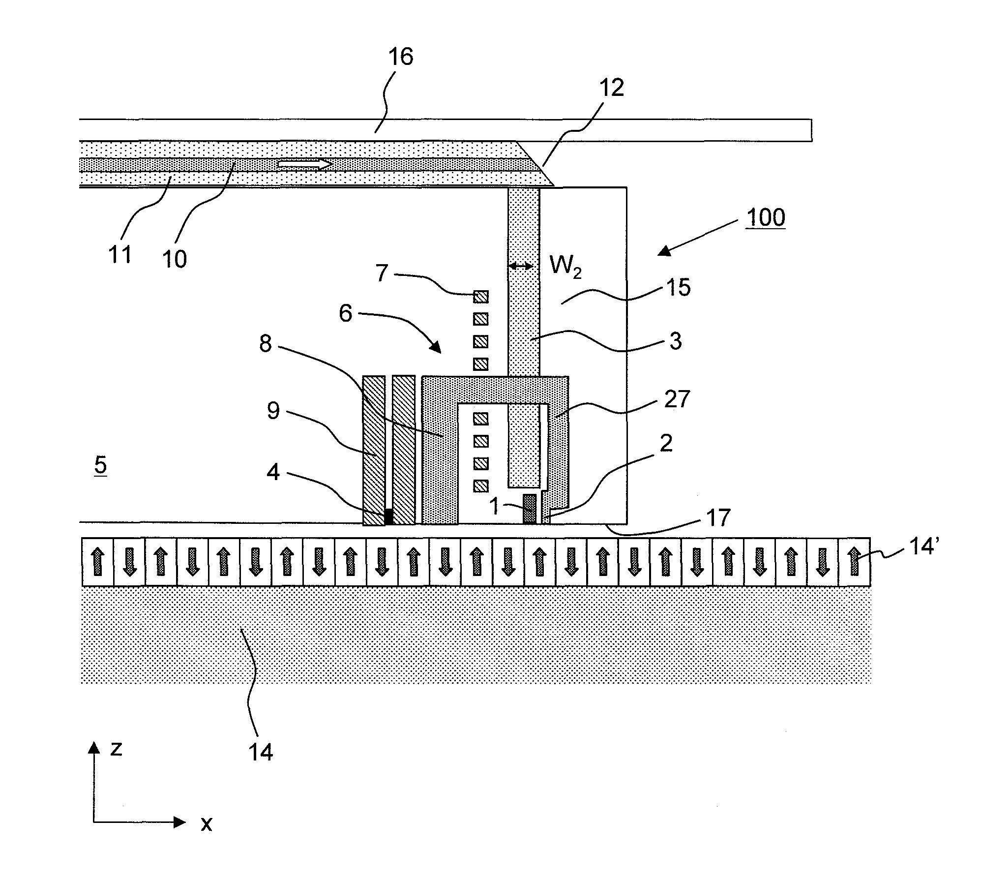
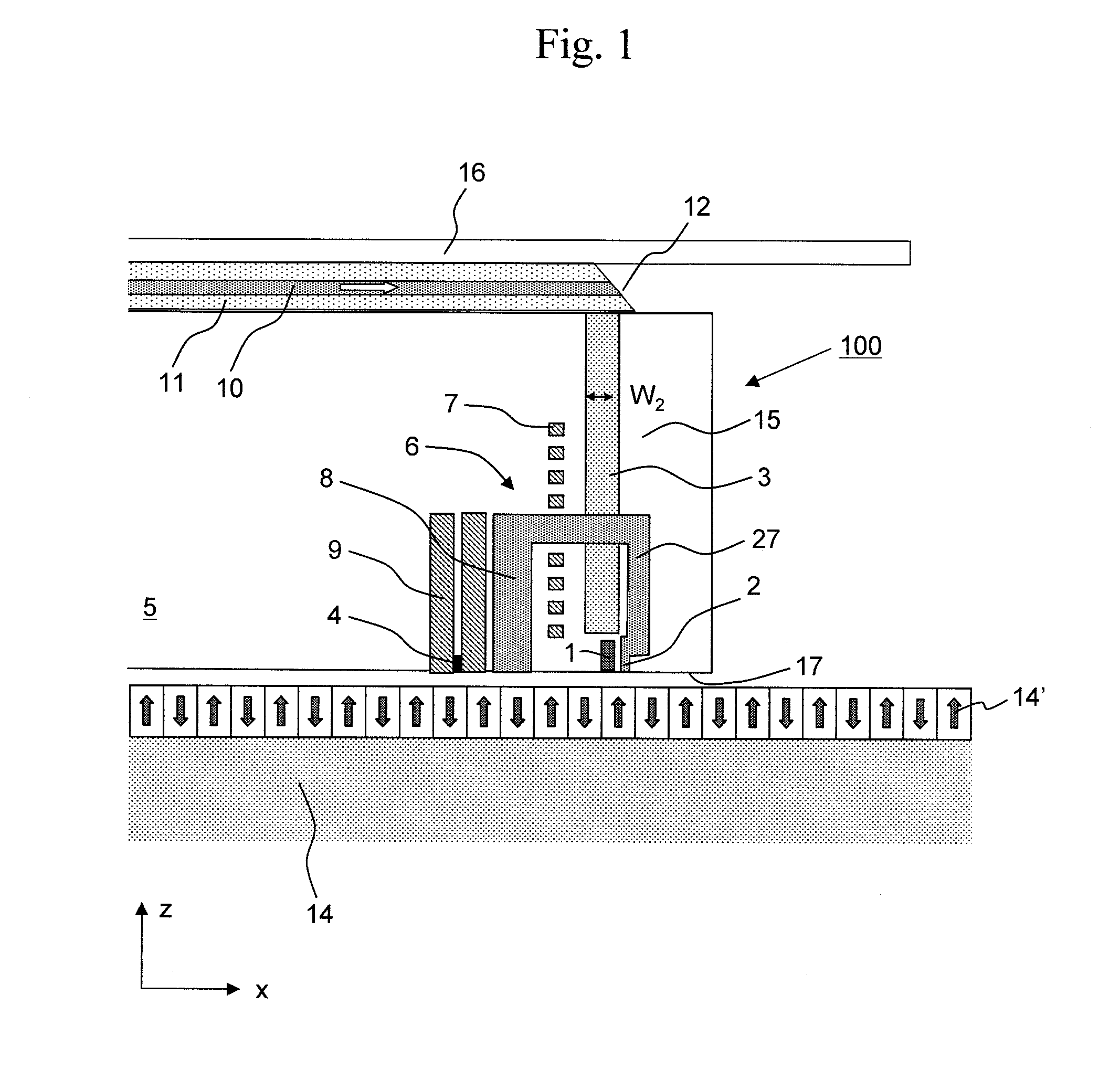
[0046]FIG. 1 shows a configuration example of a thermally assisted magnetic head 100 according to the present invention.

[0047]A semiconductor laser having a wavelength of 780 to 980 nm is used as a light source, and is installed around the base of a suspension (see reference numeral 55 in FIG. 20). A polymer waveguide 10 (a core portion shown in FIG. 1) is used to propagate light from the light source to a slider 5. The polymer waveguide 10 is placed on the suspension 16. A 45-degree mirror 12 is formed on an end surface of the polymer waveguide 10 so that the light exiting from the polymer waveguide 10 can exit in a direction orthogonal to an upper surface of the slider 5. Although the polymer waveguide 10 is used as a waveguide for propagating light from the light source to the slider 5 in this embodiment, other types of waveguides formed of quartz fiber, plastic fiber and the ...


PUM

PropertyMeasurementUnit
lengthaaaaaaaaaa
lengthaaaaaaaaaa
heightaaaaaaaaaa

Abstract

In a thermally assisted recording head using a conductive scatterer as an optical near-field transducer, a propagation loss in a waveguide for guiding light to the scatterer is reduced. An optical near-field is generated by using the conductive scatterer having a width that gradually becomes smaller toward a vertex at which the optical near-field is generated. At the same time, a height of the conductive scatterer for generating the optical near-field is made substantially equal to a height of a main pole or longer than the height of the main pole.

Description

TECHNICAL FILED[0001]The present invention relates to a thermally assisted recording head and a thermally assisted recording device.BACKGROUND ART[0002]In recent years, a thermally assisted recording method has been proposed as a recording method achieving a recoding density of 1 Tb / in2 or higher (H. Saga, H. Nemoto, H. Sukeda, and M. Takahashi, Jpn. J. Appl. Phys. 38, Part 1, 1839 (1999)). Conventional magnetic recording devices have a problem that information recorded at a recoding density of 1 Tb / in2 or higher may be lost due to thermal fluctuations. Although the coercivity of a magnetic recording medium needs to be increased to prevent the above problem, an excessive increase of the coercivity disables the formation of recording bits on the medium because of the limitation to the intensity of the magnetic field that the recording head can generate. To solve this problem, in the thermally assisted recording method, the coercivity of a medium is reduced by heating the medium with ...

Claims


Application Information

Patent Timeline
Patent Type & Authority Patents(United States)
IPC IPC(8): G11B11/00
CPCG11B5/314G11B5/4866G11B5/1278G11B2005/0021G11B2005/001
Inventor MATSUMOTO, TAKUYA
Owner HITACHI LTD
Why Eureka
Try Eureka