Non-clogging non-pressure compensated drip emitter
a drip emitter and non-pressure compensation technology, applied in the field of irrigation equipment, to achieve the effect of eliminating clogging and reducing the potential for clogging
- Summary
- Abstract
- Description
- Claims
- Application Information
AI Technical Summary
Benefits of technology
Problems solved by technology
Method used
Image
Examples
second embodiment
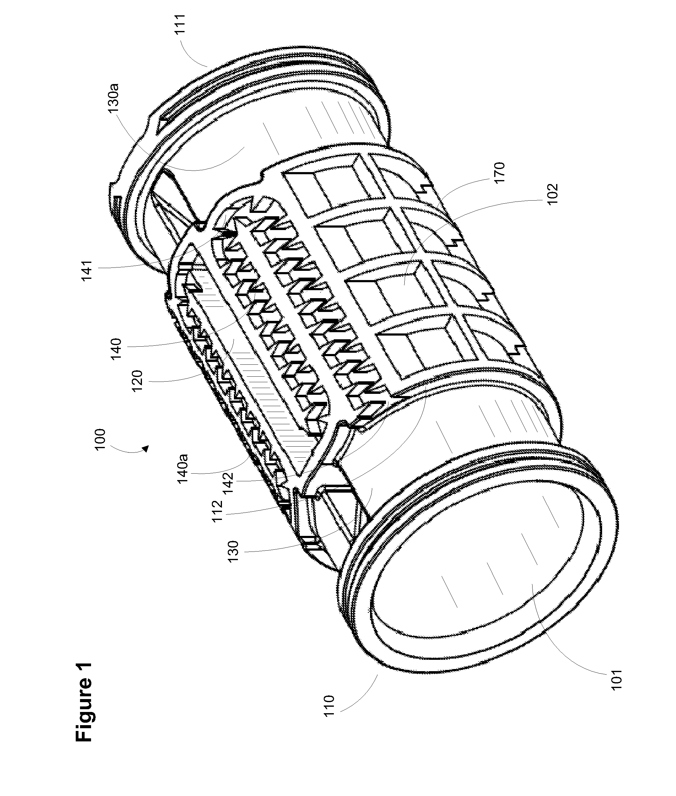
FIG. 8 is a perspective view of the non-clogging non-pressure compensated drip emitter. In this embodiment inwardly offset filter 120a is formed offset from the center looking down onto the emitter and exits labyrinth 140 into pool 130 and 130a.
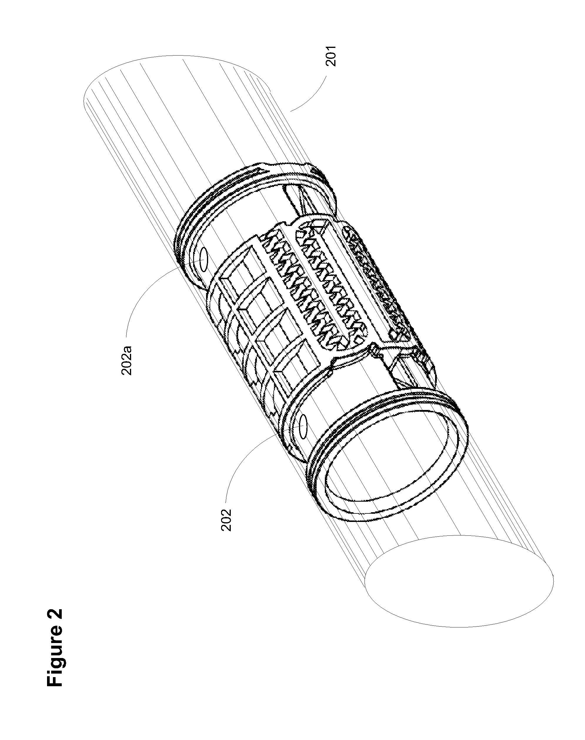
FIG. 9 is a perspective view of a second embodiment of the non-clogging non-pressure compensated drip emitter rotated 90 degrees about the lengthwise axis of the emitter and shown as situated inside pipe 201. In the figure, water flows through the labyrinth to fork 149 and exits the labyrinth at exit 142 and 142a and into the pools at each side of the emitter. Hence, this embodiment uses one labyrinth to supply two pools from one labyrinth entry point.
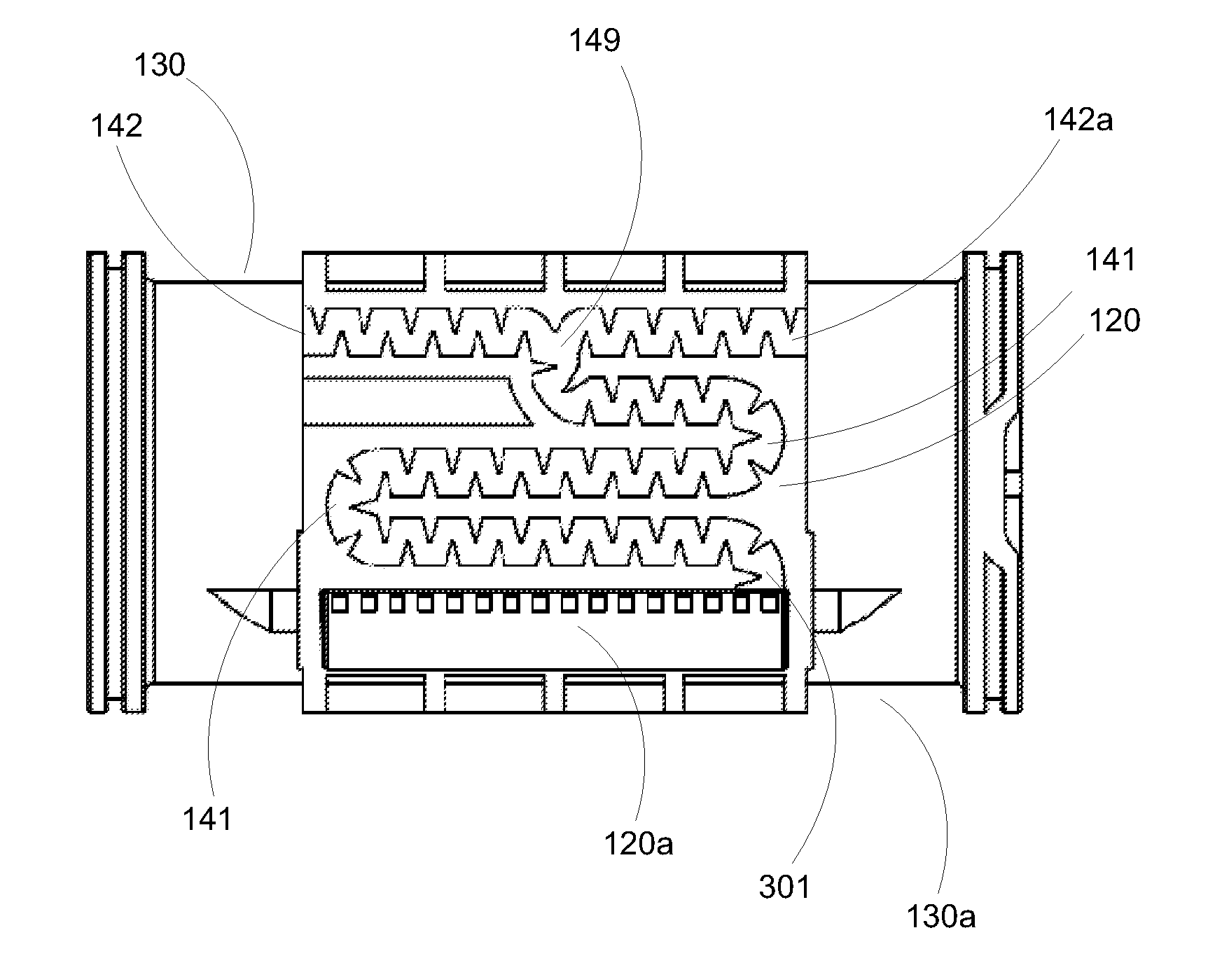
FIG. 10 is a top view of a second embodiment of the non-clogging non-pressure compensated drip emitter. In this figure, exits 142 and 142a are shown on each side of fork 149, which is a turbulent area so as to avoid clogging. There are two transfer zone locations 141 shown at the bends in the l...
third embodiment
FIG. 13 is a perspective view of the non-clogging non-pressure compensated drip emitter. In this embodiment, redundant filters 120b are situated on the top (as shown) and on the bottom of the filter (see FIG. 14). Each filter 120b leads through a respective labyrinth 140, via labyrinth entry 301, through multiple transfer zone locations 141, to labyrinth exit 142 and into a respective pool (top filter flows into pool 130, while bottom filter flows into pool 130a). The remaining reference characters are as shown in the previous embodiments.
FIG. 14 is a perspective view of a third embodiment of the non-clogging non-pressure compensated drip emitter rotated 90 degrees about the lengthwise axis of the emitter. In this figure the redundant filter 120b is shown mirrored onto the right side of the figure (as opposed to the left side mirror location of filter 120b in FIG. 13). In addition, filter 120b filters water that flows into labyrinth entry 301, through labyrinth 140 and into the righ...
fourth embodiment
FIG. 22 is a perspective view of the non-clogging non-pressure compensated drip emitter. In this embodiment filter 120c may be inwardly offset or flat with respect to the inner surface (underside as shown in the figure) of the emitter. This emitter may be placed inside a mount that is further located into a pipe or mounted with the top as shown in the figure directly against the inside of a pipe. Alternatively, more than one emitter may be mounted on a common mount and then placed inside a pipe to provide a radially redundant emitter. In this embodiment, filter 120c leads to mirrored labyrinths 140 via labyrinth entries 301 that allow water to flow into pools 130 and 130a respectively via labyrinth exits 142.
This embodiment is also a cylindrical embodiment as are the first three embodiments, however the arc of the cylinder formed by the top surface as shown is less than 360 degrees as shown in the first three embodiments of FIGS. 1-21, (the partial arc is also shown as the top surfa...
PUM
| Property | Measurement | Unit |
|---|---|---|
| depth | aaaaa | aaaaa |
| width | aaaaa | aaaaa |
| diameter | aaaaa | aaaaa |
Abstract
Description
Claims
Application Information
 - R&D
- Intellectual Property
- Life Sciences
- Materials
- Tech Scout
- Unparalleled Data Quality
- Higher Quality Content
- 60% Fewer Hallucinations
Browse by: Latest US Patents, China's latest patents, Technical Efficacy Thesaurus, Application Domain, Technology Topic, Popular Technical Reports.
© 2025 PatSnap. All rights reserved.Legal|Privacy policy|Modern Slavery Act Transparency Statement|Sitemap|About US| Contact US: help@patsnap.com


