Linear tape motor

a tape motor and tape drive technology, applied in the field of linear tape motors, can solve the problems of severe loss of expansion and contraction capability, its own problems, etc., and achieve the effects of improving the means of precision positioning objects in space, high force and power density, and operating efficiently and effectively

Inactive Publication Date: 2011-08-02
VRANISH JOHN M
View PDF18 Cites 0 Cited by
  • Summary
  • Abstract
  • Description
  • Claims
  • Application Information

AI Technical Summary

Benefits of technology

[0011]It is a principal object of the present invention to provide an improved means of precision positioning objects in space. It is also a principal object of the present invention to provide an improved means of moving and positioning objects for general use. It is a further object of the invention to position objects along a long stroke linear axis of travel and to hold position with power off. It is an object of the invention to produce high force and power density from compact packages and be capable of moving and securing large force objects at moderate to low speeds. It is an object of the present invention to operate efficiently and effectively at temperatures ranging from very low cryogenic to very high permanent magnet demagnetization. It is an object of the invention to perform with exceptional safety, reliability and durability. It is an object of the invention to be scalable with micro Linear Tape Motors moving and positioning small force objects in ultra cold temperatures to much larger Tape Motors moving and positioning very large force objects at room temperature and above. It is an option of the present invention to use construction methods and materials that are low cost and simple.
[0014]Flexure Bending is used in novel ways to enhance Linear Tape Motor performance [ref 2. Appendix A]. Bending action of the flexures connecting Back Shoe to Driver and Front Shoe to Driver provide a mechanical advantage in driving the free Shoe and the Payload which is inversely proportional to the bending angle of each Flexure. With the small angles, this mechanical advantage is large and approaches infinity as the bending angle approaches zero. Flexure Wedges included in each Shoe and in the Driver enable the secured Shoe to react the Drive force without slipping and to utilize small angle wedge and trough angles without Shoe jamming or sticking during release.

Problems solved by technology

The problem was that the “Inch Worm” used piezoelectric crystals to clamp and extend (drive) and these suffered severe loss in their expansion and contraction capabilities at ultra cold cryogenic temperatures.
This concept worked but, had its own problems.

Method used


Image

  • Linear tape motor
  • Linear tape motor
  • Linear tape motor

Examples


case 1

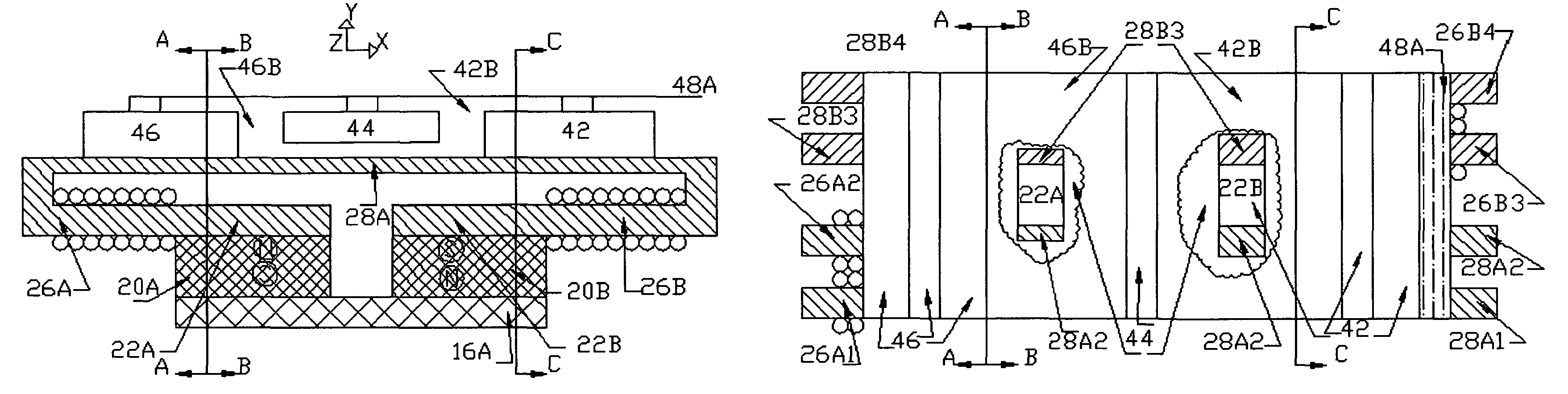
[0045]Case 1 is the worst case because all the permanent magnet flux must be forced through a single path. This requires high performance soft magnetic material that will not saturate and requires the largest NI sufficient to drive the additional magnetic flux across the air gap without changing VPm. [Eqs. 6, 7, 8 are explained in ref. 3, Appendix B.]

Permanent magnet φpm=BmaxS.

All the flux is going through the back shoe 46 air gap.

[0046]Vpm+2⁢NS⁢ISB=∅pm⁢Rair=Bmax⁢dμ0(eq.⁢6)

This requires 2.65 amps in electromagnetic assistance.

Zero flux is going through the front shoe 42 air gap.

Vpm−NSISF=0  (eq. 7)

This requires 1.33 amps in electromagnetic blocking

Zero flux is going through the driver 44 air gap.

Vpm−NDID=0  (eq. 8)

This also requires 1.33 amps in electromagnetic opposition.

The power supply requirement is, then, 5.31 amps. These are reasonable numbers.

Case 2

[0047]In Case 2, the back shoe 46 is planted, the driver 44 is being driven downwards and the front shoe 42 is free to move. The ...

case 2

g the Payload forward using magnetic force on the Driver. We assume the permanent magnet flux is equally distributed between the Back Shoe and the Driver.

[0067]∅B=∅D=∅PM2;BB=BD=BPM2∅F=0;BF=0

And from eq.9.

[0068]FB=FD=FPM22⁢⁢(6⁢⁢lbf⁢⁢for⁢⁢our⁢⁢example)⁢⁢FF=0(P11)

case 3

g the system with power off and the Driver down.

[0069]∅B=∅D=∅F=∅PM3;BB=BD=BF=BPM3⁢⁢FB=FD=FF=FPM32⁢⁢(83⁢⁢lbf⁢⁢for⁢⁢our⁢⁢example)(P12)

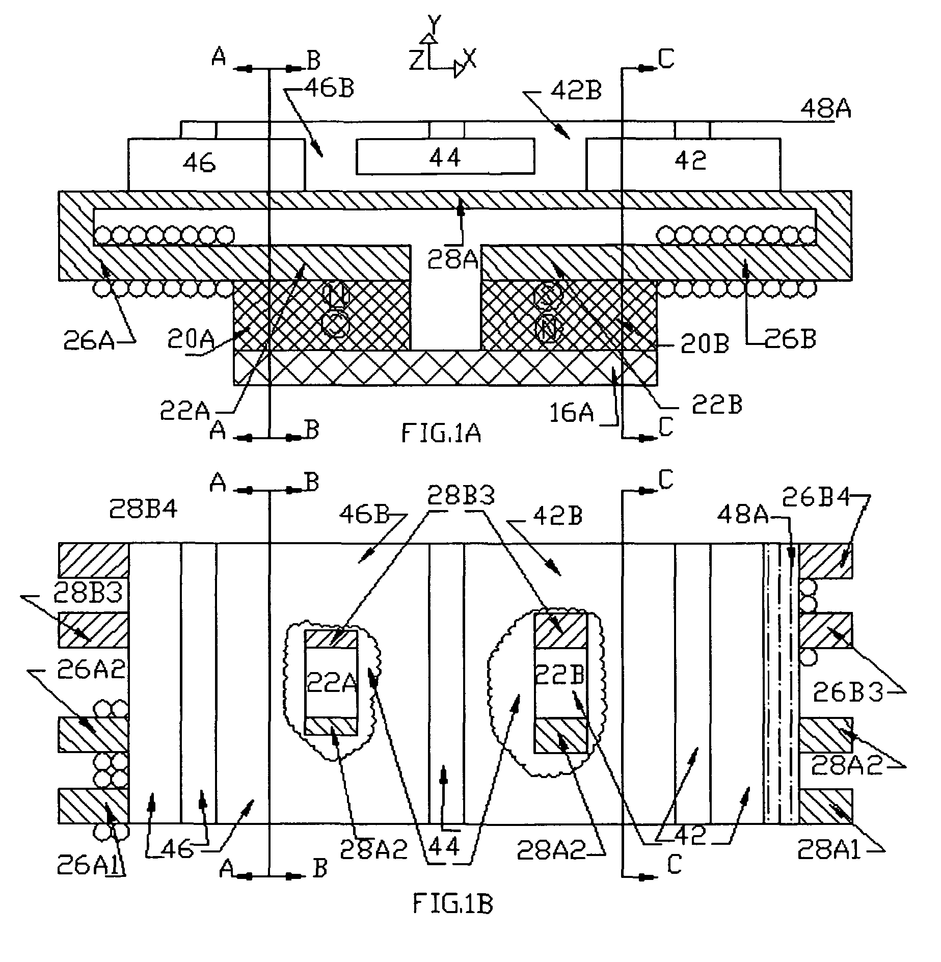
Cases 1 and 2 have mirror Cases in which the Front shoe is planted rather than the Back Shoe but, the relationships and values are unchanged.

Choosing drive flexure 46d, 42d spring stiffness to provide 2 lbf force at 0.010 deflection enables the 8 / 3 lbf available power off magnetic force to hold the driver 42 down during actuator rest and still drive it with 21 lbf·28.68=57.36 lbf.

Prototype drive would be >57.36 lbf.  (P13)

Flexure Wedge Hold Forces.

The hypothetical prototype will be examined as a means of answering this question.

Forces Reacted by Flexure Wedge Insertion.

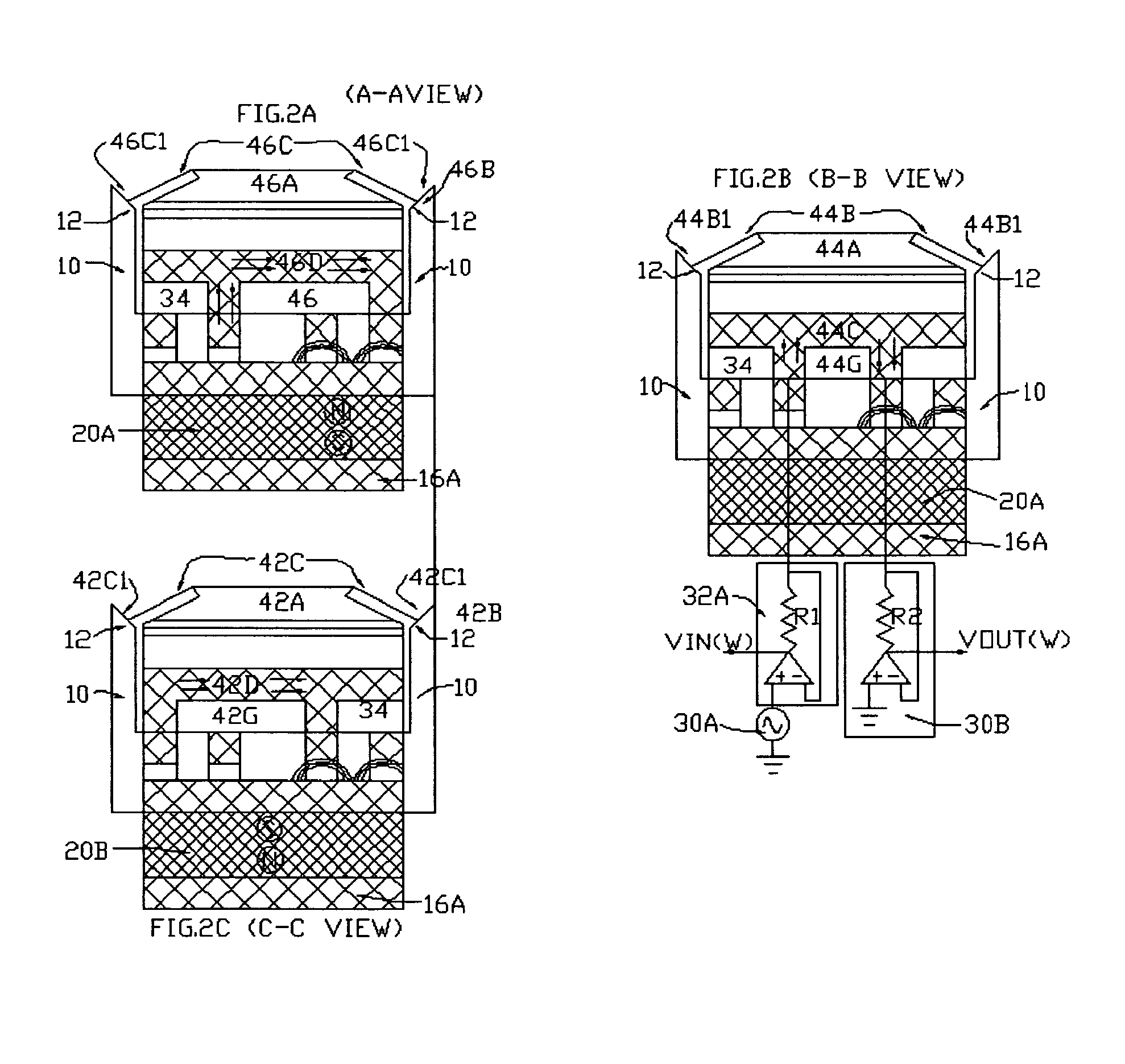
For flexure wedges 42c, 46c, 44b

[0070]Σ⁢⁢FY=0⁢⁢2⁢FN⁢sin⁢⁢θ+2⁢P=FI(eq.⁢20)FN=[2⁢L⁡(∅2)⁢sin⁢⁢θ-2⁢L⁡(1-sin⁢⁢∅∅)]⁢AE2⁢L(eq.⁢21)FN=[(∅2)⁢sin⁢⁢θ-(1-sin⁢⁢∅∅)]⁢AE⁡(by⁢⁢simplification)(eq.⁢22)P⁢⁢cos⁢⁢θ=2⁢EI⁢⁢tan⁢⁢∅L2(eq.⁢23)2⁢FNFI=G⁢⁢M⁢⁢A⁡(geometric⁢⁢mechanical⁢⁢advantage)(eq.⁢24)G⁢⁢M⁢⁢A·μS=F⁢⁢F⁢⁢...


PUM


Abstract

A Linear Tape Motors sequentially bends flexures to precisely position a payload within a large, linear range. Movement is backlash free. Flexure bending is also used to drive large forces, using efficient mechanical advantage, anchor the Tape Motor against back-slipping and prevent sticking and jamming malfunctions. Existing permanent magnet motor drive technology can be easily adapted to energize and control the flexure bending motions. Combining flexures with rare earth permanent magnets, provides ultra compact Linear Tape Motors with very high power and force densities that hold position with power off. Their operating range can be is as long as required. Thus, Linear Tape Motors are attractive for space science instruments, where precision positioning in ultra cold operating conditions is required and where low mass and low power are premium. But, they will be attractive to many other applications as well, especially where long range, safe, precise movements of large force payloads are required, where simplicity and reliability are important, where speeds are moderate to low and where operating temperatures are not so extreme as to demagnetize the permanent magnets. The Linear Tape Motor concept is novel but, it is simple and is easily adapted to modern permanent magnet motor technology, both the hardware materials and construction methods and the electronics and computer technology that controls the hardware. Development should be short and inexpensive, with high prospects of success.

Description

[0001]The rights to both inventions are held by the United States Government. The teachings of these related applications are herein meant to be incorporated by reference.CROSS REFERENCE TO RELATED APPLICATION[0002]The invention is related to an invention shown and described in Vranish, J. M., Stepping Flexures, U.S. Pat. No. 7,504,921, Mar. 17, 2009. The rights to this invention are held by the United States Government. The invention is, also related to an invention shown and described in Vranish, J. M., Driven Ground, application Ser. No. 11 / 535,872 filed Sep. 27, 2006 to PTO (filed as Device, System and Method for Sensing Electrical Circuit GSC 15,042-1.BACKGROUND OF THE INVENTION[0003]Precision pointing and positioning systems are widely used in telescopic systems making observations from space. The requirements on these systems are extreme. Their precision positioning requirements are extreme as are the extreme cold temperatures in which they must perform and the severe limitat...

Claims


Application Information

Patent Timeline
Patent Type & Authority Patents(United States)
IPC IPC(8): H02K41/02
CPCH02K41/03
Inventor VRANISH, JOHN M.
Owner VRANISH JOHN M
Why Eureka
Try Eureka