
Improved traffic light assembly

Active Publication Date: 2022-06-30
ESKP3 PTY LTD
View PDF4 Cites 0 Cited by
  • Summary
  • Abstract
  • Description
  • Claims
  • Application Information

AI Technical Summary

Benefits of technology

The present invention is a traffic light assembly that uses a unique code to communicate with driverless vehicles. The assembly includes a screen or bulbs to generate the light signals. The light signals are designed to be consistent with the driver's reaction, so they can make safe decisions. The assembly can reduce accidents, deaths, and damage to traffic light poles. The driverless vehicles can detect the unique code and proceed accordingly. The advantage of the code is that it is independent of color, which makes it easier for the vehicle's sensors to interpret.

Problems solved by technology

The current landscape near traffic light signals is not always conducive to gaining the drivers attention.
The roadside is often cluttered with place names, advertising signs including neon signs and temporary road changes such that the driver is not always fully aware of the actual traffic light signals within this background of jumbled flotsam.
Red light running in Australia and other parts of the world is a major problem and causes many accidents.
Arguably, it becomes a more deliberate illegal (and dangerous) action if the driver runs a red light when the signal has been red for some time.
The direct defiance of such a signal should not only attract a fine, but also could attract a higher point penalty to bring home the message that Stop means Stop.
Some motorists have trouble obeying signals if they cannot see (or choose not to see) the signals.
Some motorists might be distracted, tired and or incompetent and may dismiss the meaning of traffic light signals to suit their circumstances.
These motorist appear to manage too often to run the red lights or fail to slow down at amber lights.
Colour blinded motorists can have difficulty distinguishing between red and green colours to varying degrees and this can also contribute to an inability to obey traffic light signals.

Method used


Image

  • Improved traffic light assembly
  • Improved traffic light assembly
  • Improved traffic light assembly

Examples


Embodiment Construction

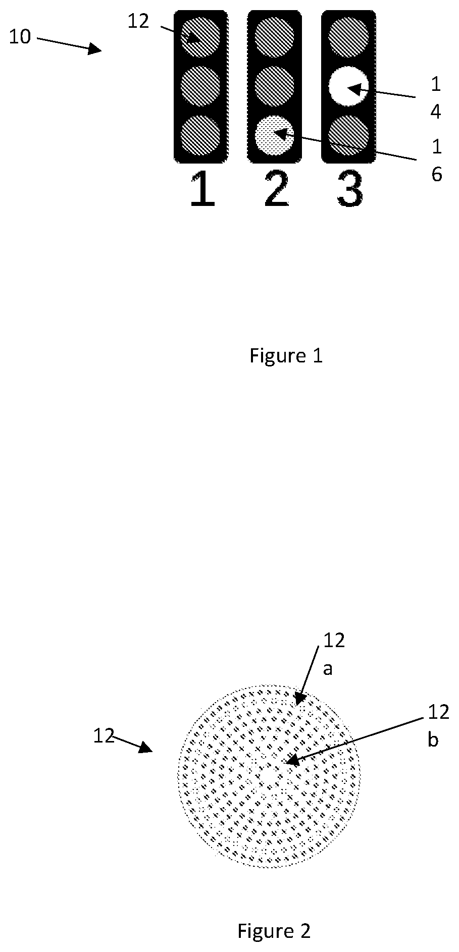
[0046]As shown in FIG. 1, the traffic light signals 10 can be of the type having three lights 12, 14, 16 arranged in a stack, with the topmost light being capable of emitting red light (1), the middle light being capable of emitting amber light (2), and the bottom light being capable of emitting green light (3). The image in FIG. 1 shows three traffic light assemblies, each with one light activated. These are the traffic lights that are most common in countries around the world. However, any orientation of traffic lights could be used as would be understood upon reading the description herein.

[0047]It is generally understood that a red light in a traffic light assembly means stop. The red light should be clearly transmitted to the person required to obey the traffic light.

[0048]In the present sequencing, when the red light is first activated, the light can be motionless for a predetermined period of time. The predetermined period of time can be at least 30, 60, 90, 120 seconds. The ...


PUM


Abstract

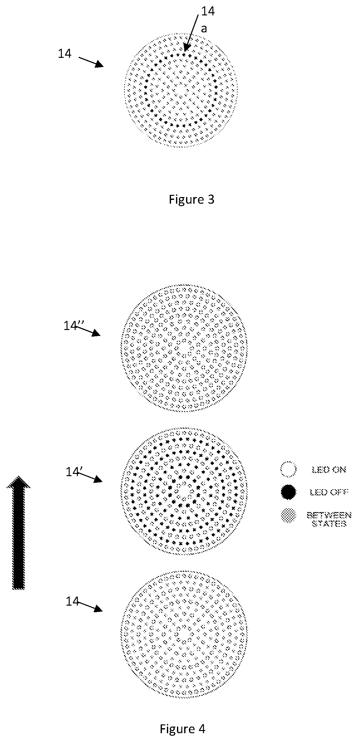
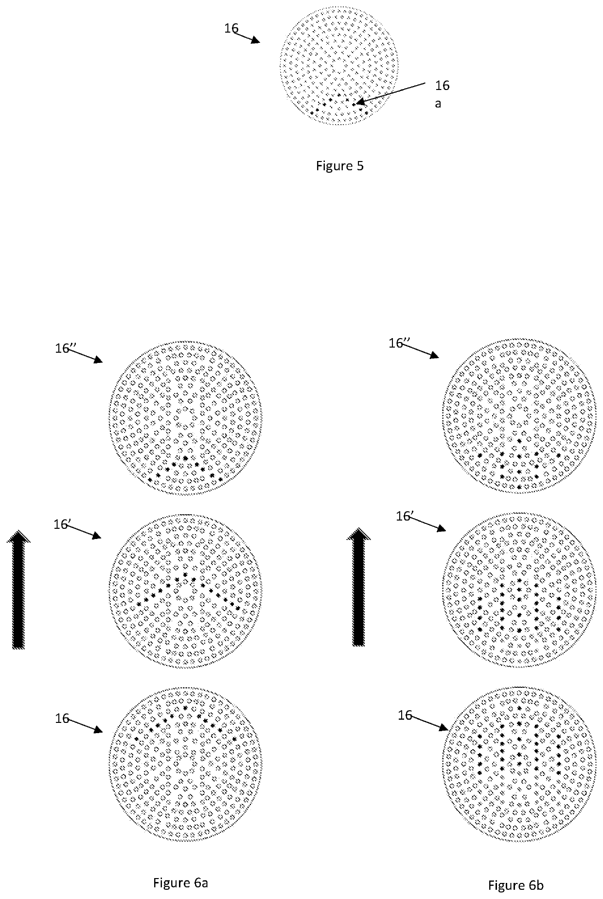
A traffic light assembly is disclosed with red, amber and green lights. While light is being emitted, a flashing sequence pattern is generated within the area to enhance the meaning of the signal communicated to the driver. The sequence pattern is formed by changing the colour of light emitted, and or by ceasing to emit light. An intermediate pattern that is different in configuration from any of the sequence patterns is provided at a transition between at least one of the red, amber and green lights to further communicate to the driver that the light signal is about to change and that action is about to be required.

Description

PRIORITY[0001]This patent application is a national phase filing under section 371 of PCT / AU2020 / 050433, filed on May 1, 2020, which claims the priority of Australian patent application 2019901493, filed on May 2, 2019 and Australian patent application 2019901944 filed on Jun. 5, 2019, each of which is hereby incorporated by reference in its entirety.TECHNICAL FIELD[0002]The present invention relates to a traffic light assembly providing a signal system. The traffic light assembly can be used to control the flow of traffic on roads or in other areas where management of traffic is required such as but not limited to factories, airports, bus stations and other transport hubs. Also disclosed is a method for controlling driverless vehicles using the traffic light assembly of the invention.BACKGROUND[0003]The current landscape near traffic light signals is not always conducive to gaining the drivers attention. The roadside is often cluttered with place names, advertising signs including ...

Claims


Application Information

Patent Timeline
IPC IPC(8): G08G1/07
CPCG08G1/07G08G1/09G08G1/096G09F2009/3055G09F13/0472G09F2013/222G09F19/20G08G1/095
Inventor KIJASHKA, ELIZABETH ABIGAEL
Owner ESKP3 PTY LTD
Learn More