LED lamp

a technology of led lamps and led lamps, which is applied in the direction of discharge tubes luminescnet screens, semiconductor devices for light sources, lighting and heating apparatus, etc., can solve the problems of electrical connection between screw-type led lamps and screw-type lamp holders, and achieve the effect of preventing electrical connection interruption

Inactive Publication Date: 2011-08-02
HON HAI PRECISION IND CO LTD
View PDF2 Cites 42 Cited by
  • Summary
  • Abstract
  • Description
  • Claims
  • Application Information

AI Technical Summary

Benefits of technology

[0007]Therefore, it is desirable to provide an LED lamp with an illumination direction thereof being adjustable.

Problems solved by technology

However, some screw-type LED lamps are designed to emit light only through a portion of an outer circumferential surface of the LED lamp.
However, after the screw-type LED lamp is turned from the first position to the second position, the screw-type lamp cap may be electrically disengaged from the screw-type lamp holder to cause an electrical connection between the screw-type LED lamp and the screw-type lamp holder to be interrupted.

Method used


Image

  • LED lamp
  • LED lamp
  • LED lamp

Examples


Embodiment Construction

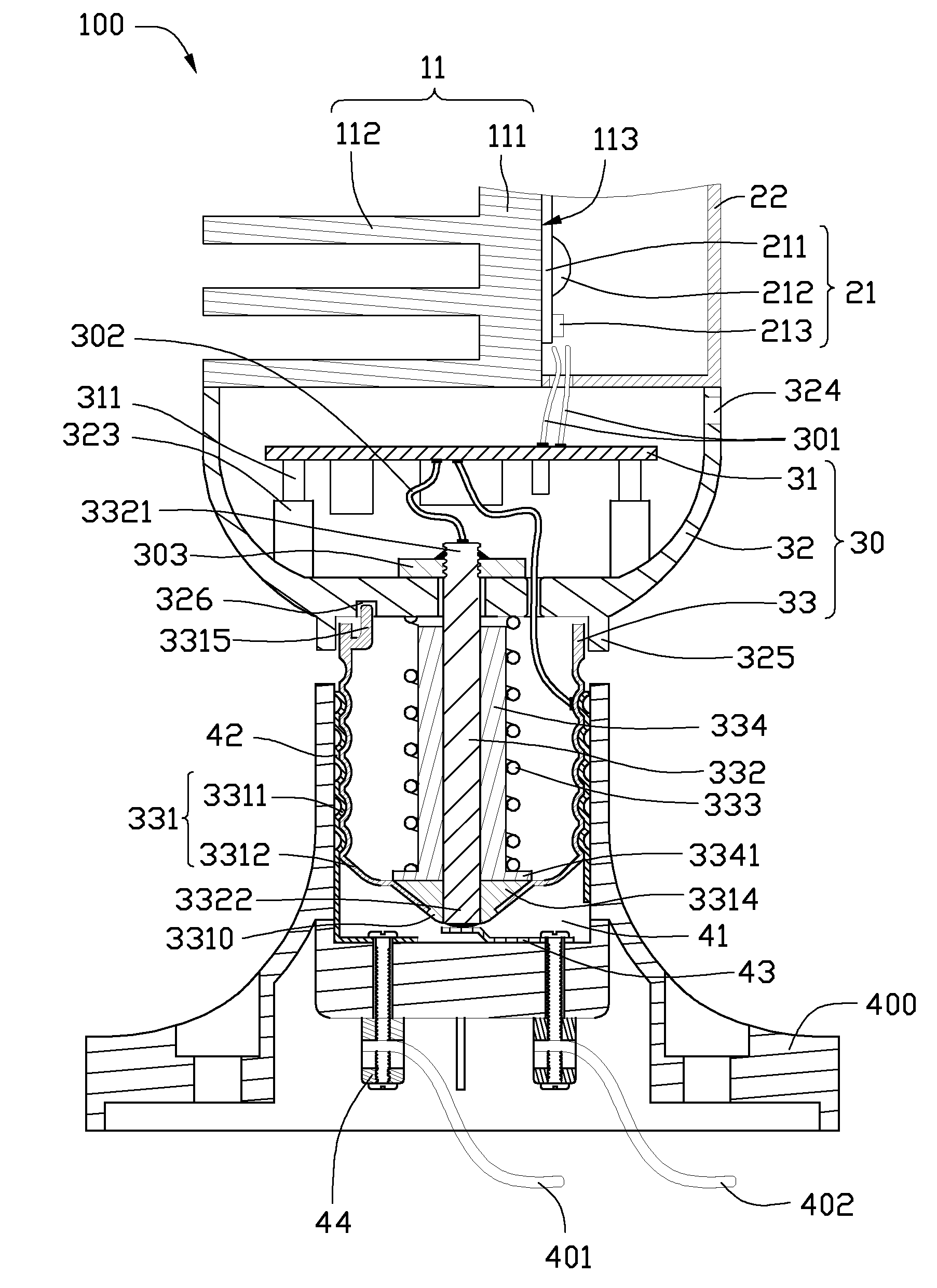
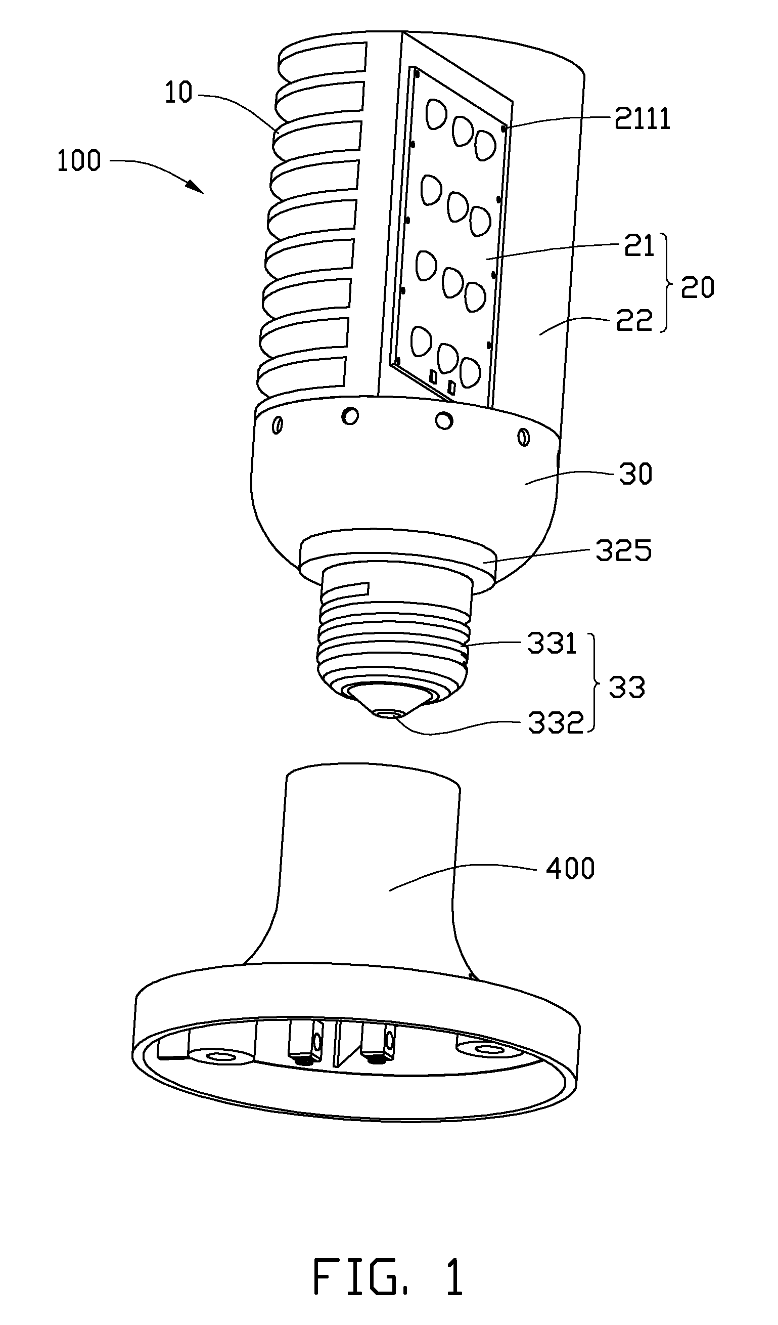
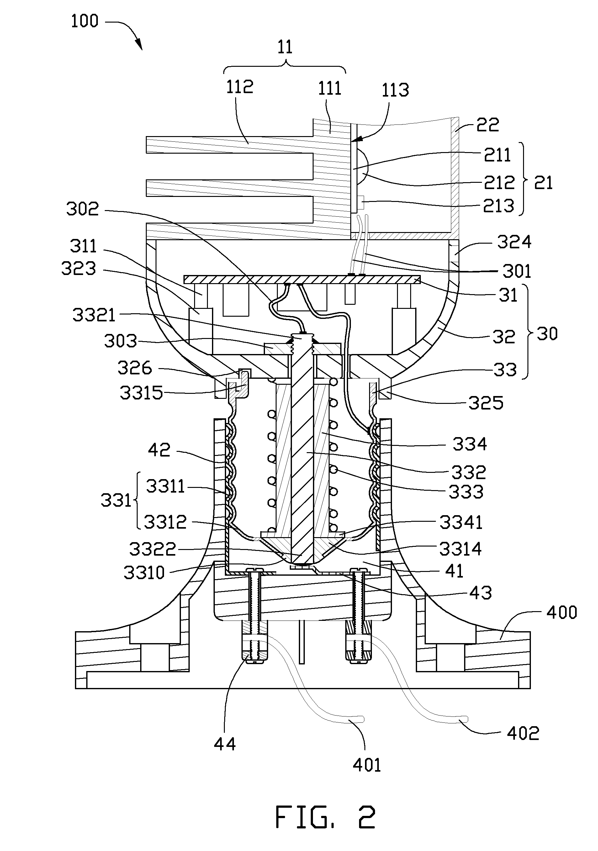
[0018]Referring to FIGS. 1 and 2, an LED lamp 100 according to a first embodiment of the present disclosure includes a heat dissipation part 10, an optical part 20, and an electric part 30. The LED lamp 100 can be mounted to a conventional lamp holder 400 to obtain electric current from an external power source to emit light.

[0019]The heat dissipation part 10 includes a heat dissipation member 11. The heat dissipation member 11 is made of a material having a high thermal conductivity, such as aluminum or aluminum alloy. The heat dissipation member 11 includes a vertical base 111 and a plurality of fins 112 extending horizontally outwardly from a left side of the base 111. The base 111 is rectangular. The fins 112 are semicircular and spaced from each other along a lengthwise direction of the base 111. A diameter of the fin 112 is equal to a width of the base 111. A right side of the base 111 forms a heat absorbing surface 113.

[0020]The optical part 20 is arranged at a right side of ...


PUM


Abstract

An LED lamp includes a heat dissipation part, an optical part and an electric part. The optical part includes an LED module attached to a heat dissipation member of the heat dissipation part and an envelope covering the LED module. The electric part includes a casing, a circuit board and a lamp cap. The casing includes a bottom plate and an annular sidewall extending from a periphery of the bottom plate to connect with the heat dissipation part and the optical part. The lamp cap includes an electric shell and an electric pole axially inserted in the electric shell. The lamp cap is rotatablely connected to the casing via the electric pole. The electric pole is fixedly connected to and electrically insulated from the electric shell. An orientation-adjusting structure is provided between the casing and the lamp cap for adjusting the illumination direction of the LED lamp.

Description

BACKGROUND[0001]1. Technical Field[0002]The disclosure generally relates to light emitting diode (LED) lamps, and particularly to an LED lamp with an adjustable illumination direction.[0003]2. Description of Related Art[0004]LEDs (light emitting diodes) are preferred for use in LED lamps rather than CCFLs (cold cathode fluorescent lamps) and other traditional lamps due to their excellent properties, including high brightness, low power consumption, long lifespan, environment friendliness, rapid start-up, directivity, and et al.[0005]Nowadays, screw-type LED lamps are widely used. The screw-type LED lamp is provided with a screw-type lamp cap at one end thereof for electrically connecting the LED lamp with an external power source. Generally, the screw-type LED lamps emit light outwardly around a whole outer circumferential surface thereof. In use, the screw-type lamp cap of the LED lamp is screwed into a screw-type lamp holder which is electrically connected with the external power ...

Claims


Application Information

Patent Timeline
Patent Type & Authority Patents(United States)
IPC IPC(8): H01J1/62
CPCF21S6/002F21V29/83F21K9/1355F21V29/507F21V29/763F21K9/58F21V29/004F21Y2101/02F21Y2103/003F21K9/23F21K9/65F21Y2103/10F21Y2115/10F21K9/238F21K9/235
Inventor LIU, TAY-JIAN
Owner HON HAI PRECISION IND CO LTD
Why Eureka
Try Eureka