Harness for kiteboarding
a kiteboarding and harness technology, applied in the field of harnesses for kiteboarding, can solve the problems of reducing the overall enjoyment of kiteboarding by kiteboarders, affecting the performance or comfort of harnesses, and premature fatigue of kiteboarders
- Summary
- Abstract
- Description
- Claims
- Application Information
AI Technical Summary
Benefits of technology
Problems solved by technology
Method used
Image
Examples
first embodiment
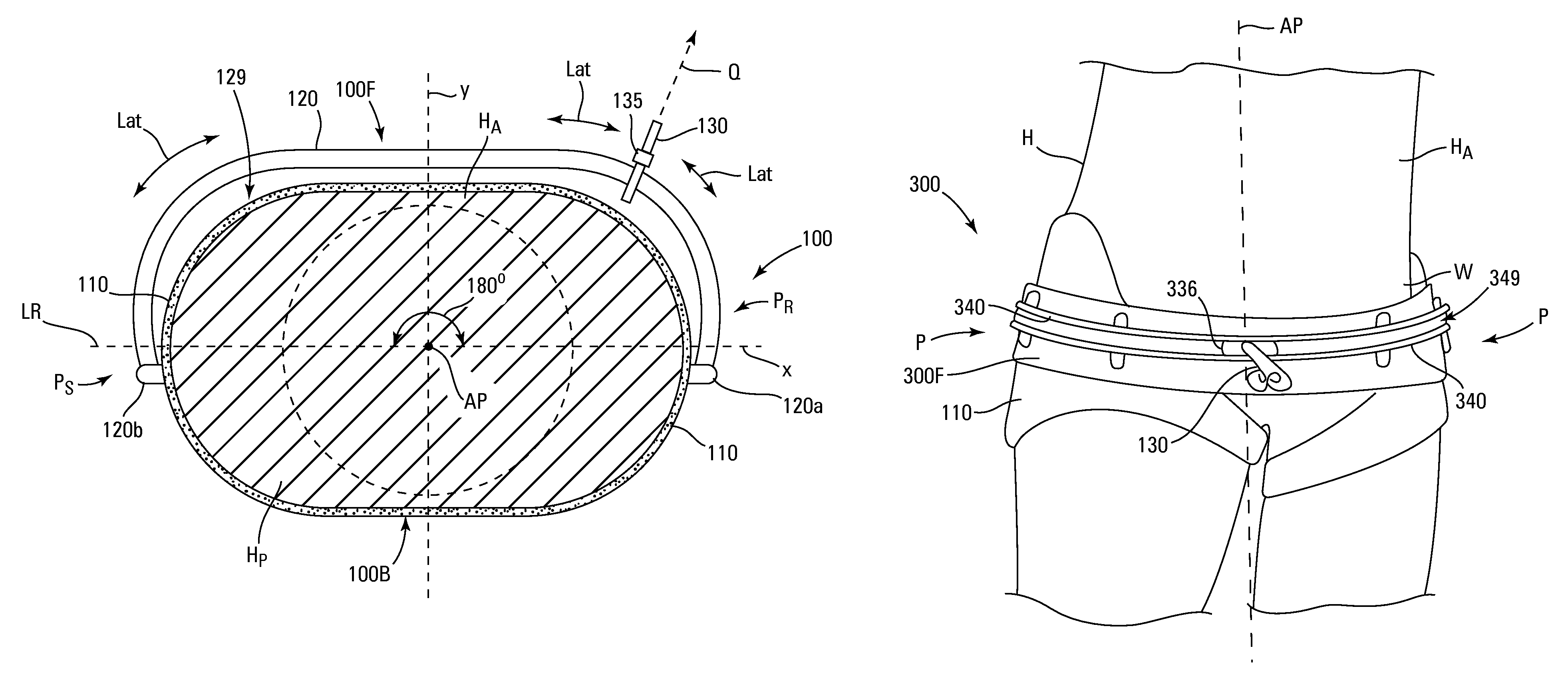
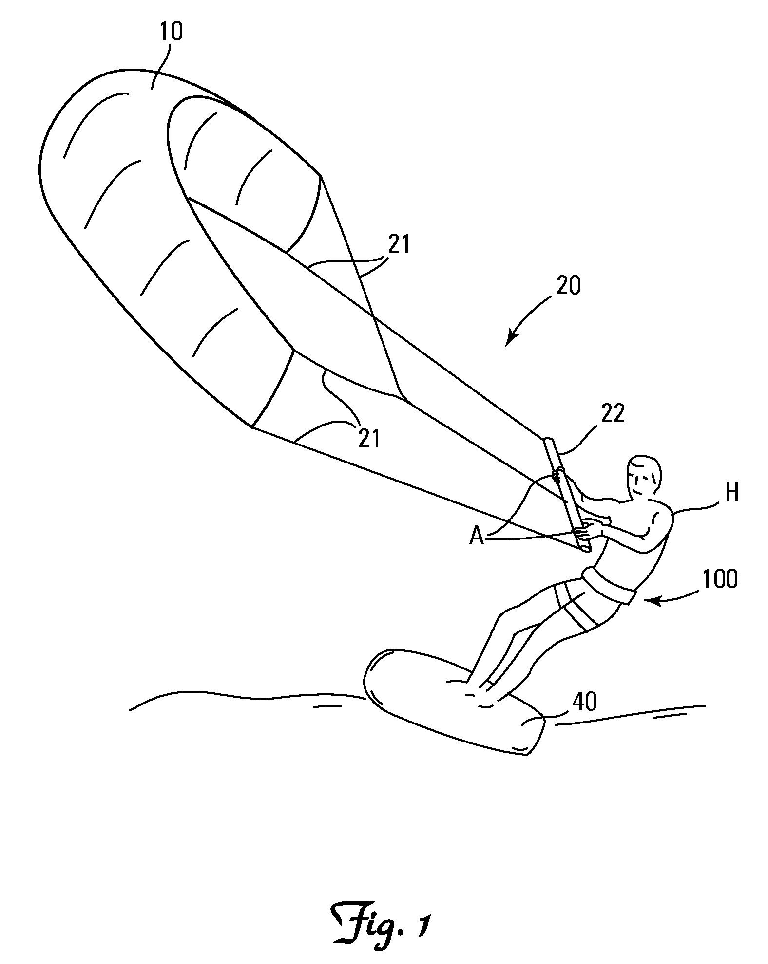
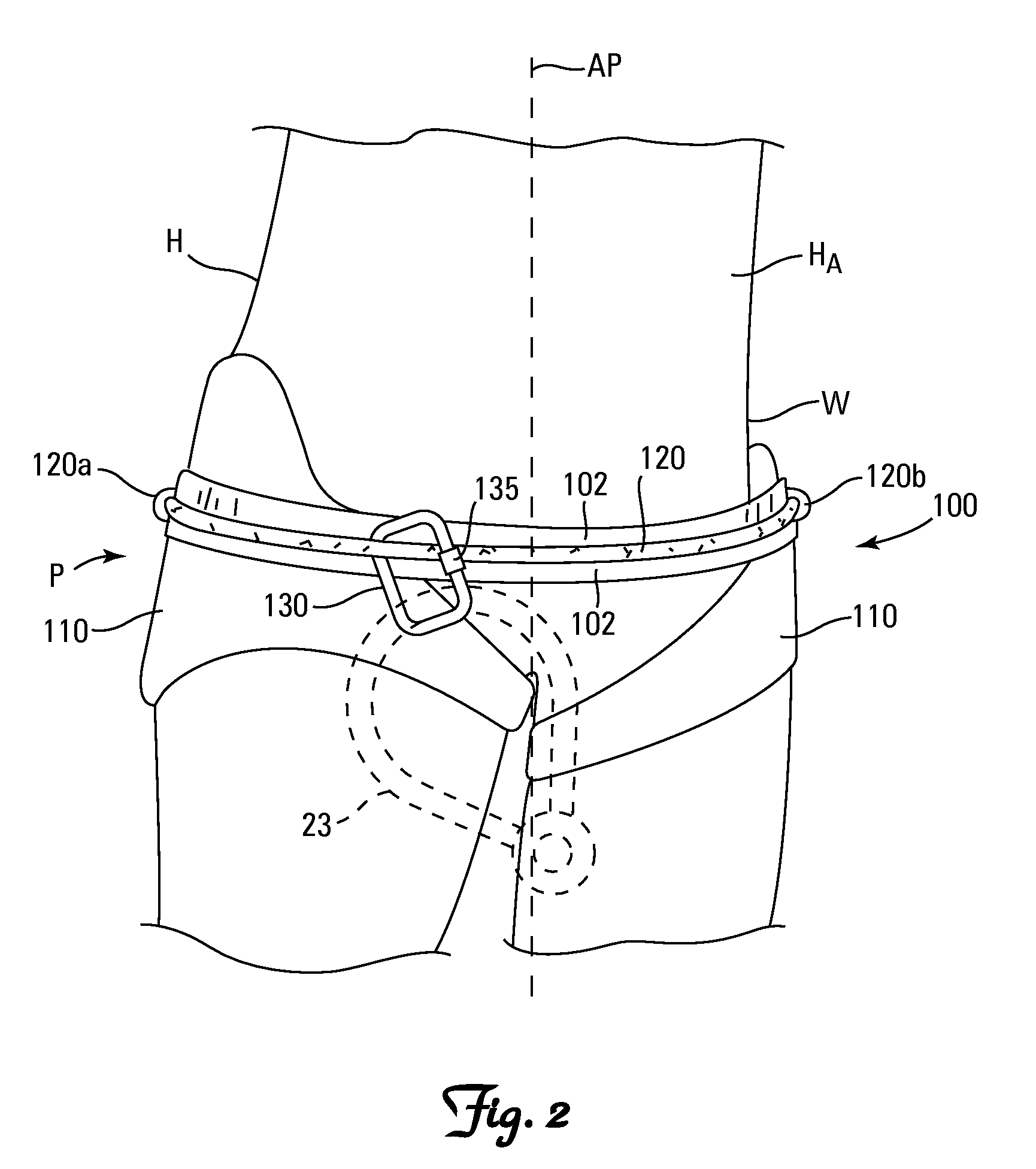
[0023]A first embodiment of the harness 100 is shown in FIGS. 1-3. The harness 100 has a front 100F and a back 100B, and includes a girdle 110, a guide line 120, and a hook 130. A laterally Lat extending backing strap 102 may be provided underneath (i.e., medial) the guide line 120 for facilitating sliding of the hook 130 along the guide line 120 and / or preventing the hook 130 from rubbing against a wearer H as the hook 130 slides along the guide line 120. The hook 130 secures a kite 10 to the harness 100 via conventional rigging 20 such as flight lines 21, a control bar 22 and a chicken loop 23. The hook 130 is attached to the guide line 120 so that it can slide laterally Lat along the length of the guide line 120 about the anteroposterior axis AP of a wearer H. The guide line 120 on the first embodiment of the harness 100 is attached at each end 120a and 120b to the girdle 110 so as to permit the hook 130 to slide along the guide line 120 in excess of 180° about the anteroposterio...
second embodiment
[0041]FIG. 4 shows a second embodiment of the harness 200 with a front portion 200F and a rear portion 200B separated by the coronal plane x. The second embodiment of the harness 200 substantially resembles the first embodiment of the harness 100, except that the guide line 120 encircles the pelvis P with a single point of attachment 120a in the median plane y. By providing a single point of attachment the hook 130 can slide nearly 360° along the guide line 120 around the pelvis P.
third embodiment
[0042]FIGS. 5 and 6 show a third embodiment of the harness 300 with a front portion 300F and a rear portion 300B separated by the coronal plane x. The third embodiment of the harness 300 substantially resembles the second embodiment of the harness 200, except that the guide line 120 is replaced with a track 340.
[0043]The track 340 encircles the pelvis P and includes a C-shaped lateral channel 349. A head 336 is provided on the proximal end of the hook 130 for sliding engagement within the channel 349 in the track 340.
[0044]The track 340 can be made from any material capable of bearing the pull forces Q exerted by the kite 10. Preferred materials include metals, such as aluminum and steel, and plastics, such as polyurethane.
[0045]The third embodiment of the harness 300 provides several significant advantages. First, the harness 300 permits the hook 130 to slide completely around the pelvis P, thereby permitting a kiteboarder H to rotate 360° or more relative to the kite 10 without wr...
PUM
 Abstract
Description
Claims
Application Information
 - R&D
- Intellectual Property
- Life Sciences
- Materials
- Tech Scout
- Unparalleled Data Quality
- Higher Quality Content
- 60% Fewer Hallucinations
Browse by: Latest US Patents, China's latest patents, Technical Efficacy Thesaurus, Application Domain, Technology Topic, Popular Technical Reports.
© 2025 PatSnap. All rights reserved.Legal|Privacy policy|Modern Slavery Act Transparency Statement|Sitemap|About US| Contact US: help@patsnap.com


