Multi-tube solar collector structure

a solar collector and multi-tube technology, applied in solar heat collectors with working fluids, solar heat collectors for particular environments, solar-ray concentration, etc., can solve the disadvantage of loss occasioned by the need for multiple reflections, the collector system of the second group (i

Inactive Publication Date: 2011-08-09
AREVA SOLAR
View PDF28 Cites 34 Cited by
  • Summary
  • Abstract
  • Description
  • Claims
  • Application Information

AI Technical Summary

Problems solved by technology

Collector systems of the first group suffer the disadvantages that the absorber tube collects incident solar energy from one only reflector element and requires complex mounting and fluid coupling arrangements.
Collector systems of the second group largely avoid the disadvantages of the first group but suffer the disadvantage of losses occasioned by the need for multiple reflections, firstly from ground-mounted reflectors and then from the inverted trough reflectors.
Moreover, collector systems of the second group (if not both groups) suffer a relatively high emissivity-to-absorptance ratio as a consequence, in part, of the surface area-to-aperture ratio attributable to the relatively large diameter tube required of a single-tube collector system.
Furthermore, as a secondary issue, collector systems of both the first and second groups suffer loss of operating efficiency due to movement of unconfined heated air from the interior of the trough-like reflectors.
Still further, as a tertiary issue, to the extent that the collector systems of the first and second groups employ a single absorber tube, those collector systems are not capable of providing for a variable absorption aperture.

Method used


Image

  • Multi-tube solar collector structure
  • Multi-tube solar collector structure
  • Multi-tube solar collector structure

Examples


Embodiment Construction

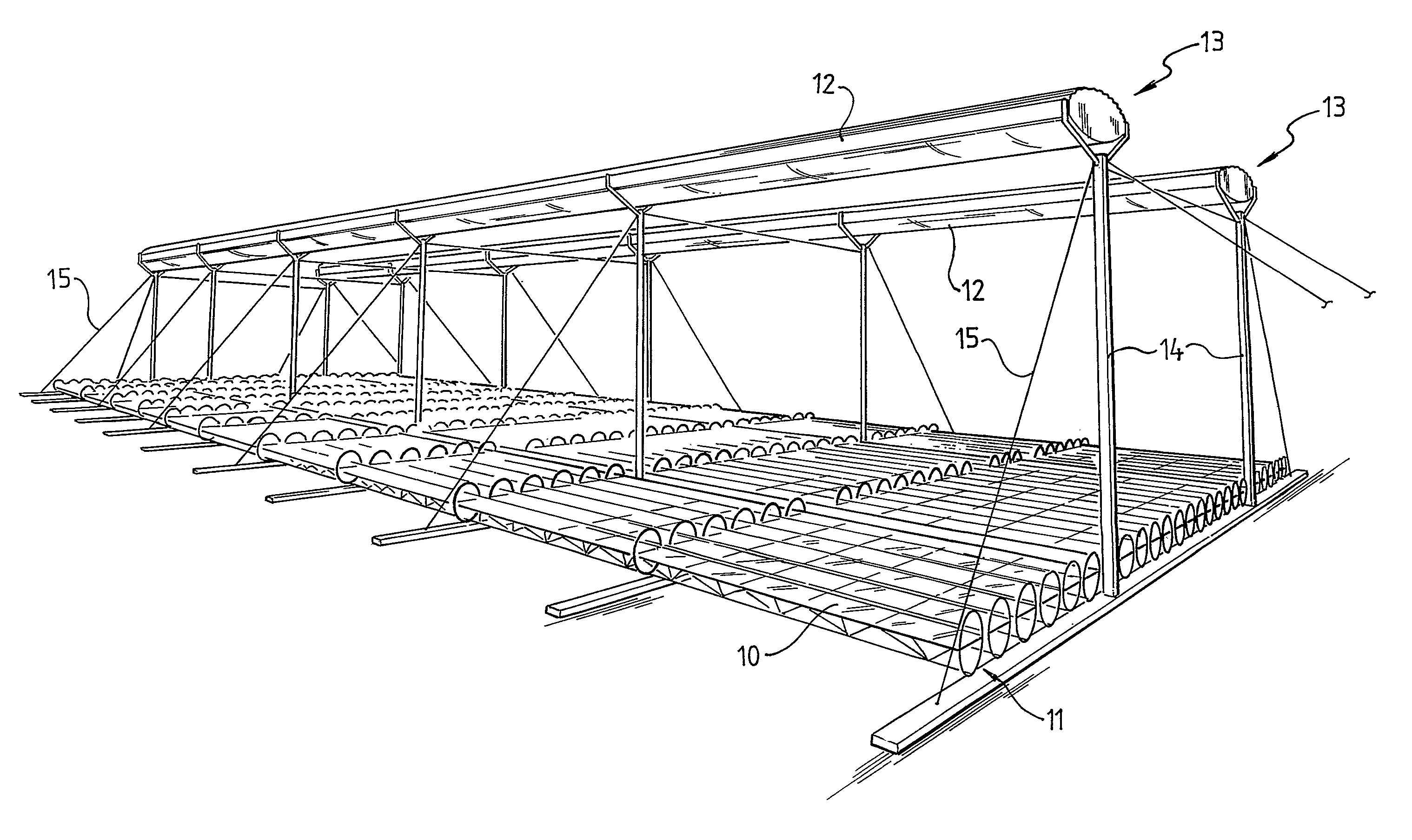
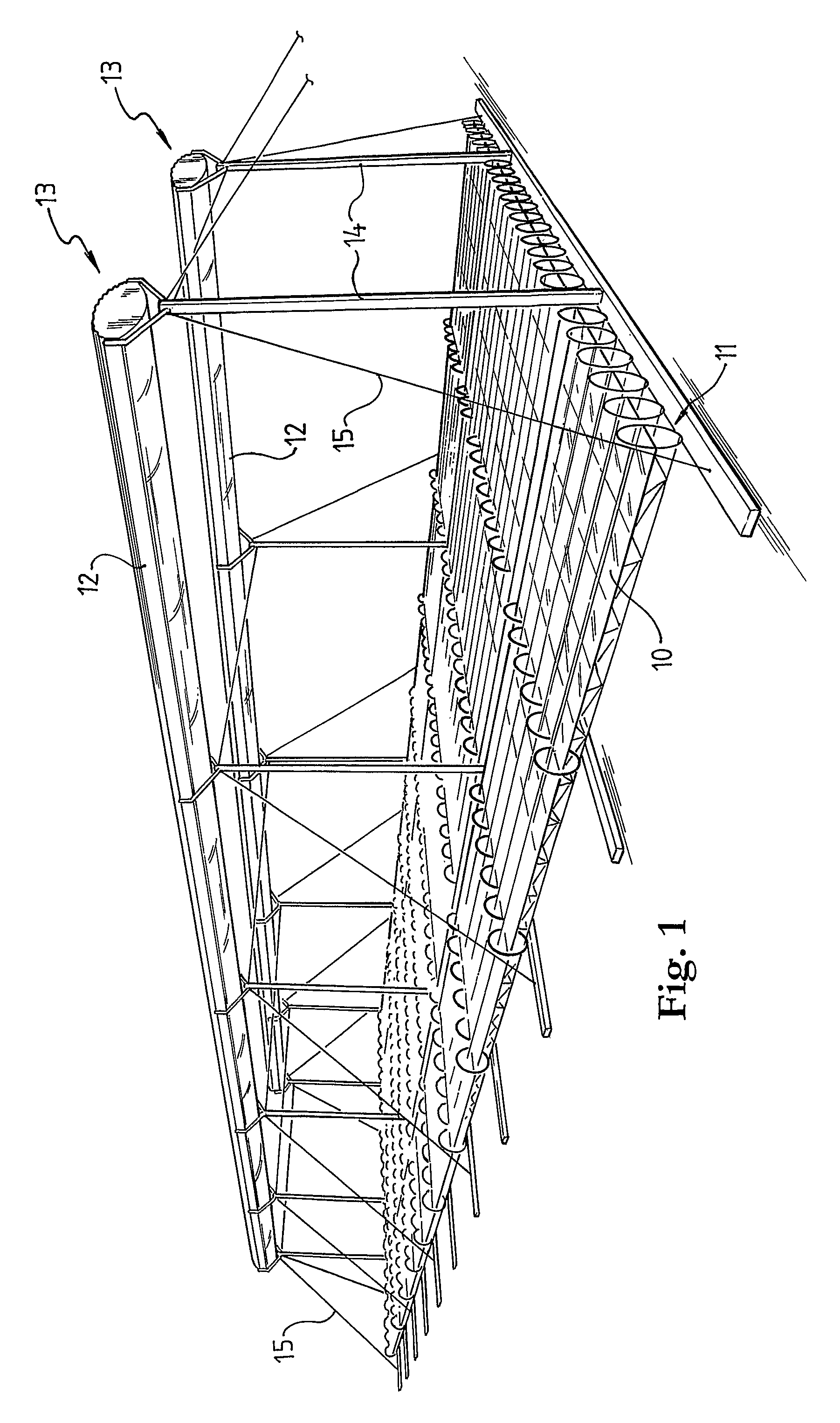
[0023]As shown in FIGS. 1 to 3, the CLFR system comprises a field of ground mounted reflectors 10 that are arrayed in rows 11 and further comprises parallel collector systems 12, each of which is constituted by aligned collector structures 13. A complete CLFR system might occupy a ground area within the range 5×101 m2 to 25×106 m2 and the system as illustrated in FIG. 1 may be considered as a portion only of a larger CLFR system.

[0024]The reflectors 10 may be of the type described in co-pending International Patent Applications numbered PCT / AU2004 / 000883 and PCT / AU2004 / 000884, filed 1 Jul. 2004 by the present Applicant, and the disclosures of these Patent Applications are incorporated herein by reference.

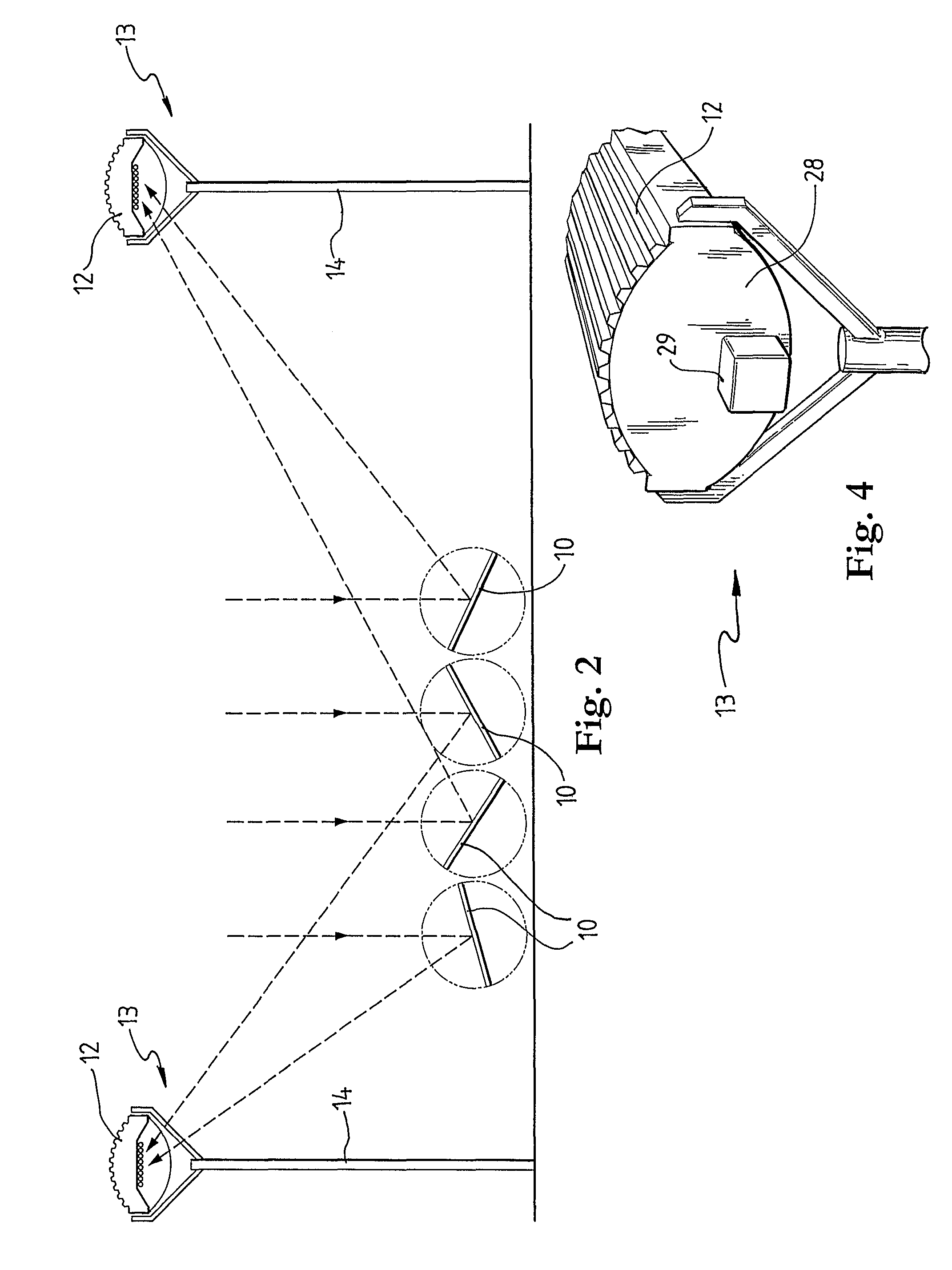
[0025]The reflectors 10 are driven collectively or regionally, as rows or individually, to track movement of the sun (relative to the earth) and they are orientated to reflect incident radiation to respective ones of the collector systems 12, as shown schematically and by way of exa...


PUM


Abstract

A collector system (12) is disclosed that comprises a row of linearly conjoined collector structures (13). The collector system is arranged to be located at a level above a field of reflectors (10) and to receive solar radiation reflected from the reflectors within the field. The collector structure (13) comprises an inverted trough (16) and, located within the trough, a plurality of longitudinally extending absorber tubes (30) that, in use, are arranged to carry a heat exchange fluid. The absorber tubes (30) are supported side-by-side within the trough and each absorber tube has a diameter that is small relative to the aperture of the trough. The ratio of the diameter of each absorber tube to the trough aperture dimension is of the order of 0.01:1.00 to 0.10:1.00 and, thus, the plurality of absorber tubes functions, in the limit, effectively to simulate a flat plate absorber.

Description

CROSS REFERENCE TO RELATED APPLICATIONS[0001]This application is submitted under 35 U.S.C. 371 as a U.S. National Phase application of International Patent Application Number PCT / AU2005 / 000208, filed Feb. 17, 2005, which claims priority to Australian Application Serial Number 2004900787, filed Feb. 17, 2004, Australian Application Serial Number 200400788, filed Feb. 17, 2004, and Australian Application Serial Number 200400786, filed Feb. 17, 2004, the contents of which are each hereby incorporated by reference as if recited in full herein for all purposes.FIELD OF THE INVENTION[0002]This invention relates to a solar collector structure that employs a plurality of absorber tubes that are arranged to be illuminated by solar radiation from a reflector field and to transfer absorbed energy to a heat exchange fluid that is, in use of the structure, carried by the tubes. The invention has been developed in the context of a so-called compact linear Fresnel reflector (CLFR) system and is he...

Claims


Application Information

Patent Timeline
Patent Type & Authority Patents(United States)
IPC IPC(8): F24J2/32F24J2/14F24J2/46F24J2/50F24J2/54F24S10/40F24S10/70F24S20/20F24S23/70F24S23/74F24S23/77F24S23/79
CPCF24J2/07F24J2/245F24J2/4636F24J2/464F24J2/506F24J2/54F24J2/541F24J2/05F24J2/10F24J2/242F24J2/16F24J2002/1076F24J2002/108F24J2002/5468Y02E10/41Y02E10/44Y02E10/47F24J2002/1023F24S80/525F24S40/80F24S80/40F24S20/20F24S30/425F24S2023/872F24S10/742F24S30/40F24S2030/136F24S23/77F24S10/40F24S23/70F24S10/72F24S2023/834F24S2023/87Y02E10/40
Inventor LE LIEVRE, PETER
Owner AREVA SOLAR
Why Eureka
Try Eureka