Anesthetic vaporizer

a technology of anesthetic vaporizer and vaporizer chamber, which is applied in the direction of machine/engine, process and machine control, and combustion gas purification/modification, etc., can solve the disadvantages of position and maximum concentration mark, the inability to achieve concentration marks with these dispensing grooves on the setting wheel, and the inability to achieve concentration marks. , to achieve the effect of increasing or decreasing the effective length of the gas channel, reducing the effect of gas channel resistance and increasing the variation

Inactive Publication Date: 2011-08-09
DRAGERWERK AG
View PDF14 Cites 2 Cited by
  • Summary
  • Abstract
  • Description
  • Claims
  • Application Information

AI Technical Summary

Benefits of technology

[0012]The advantage of the present invention is essentially that two dispensing channels in the form of grooves are provided as the dispensing element, which have either a constant or variable height or width along the direction of gas flow and are coupled with one another in terms of flow on one side by means of a connection channel. The dispensing channels extend extensively radially, concentrically with constant, but different radii. A setting range of more than 300° can thus be obtained, and the gas path that can be used for the dispensing is up to twice as long due to the dispensing channels extending in parallel, as a result of which the dispensing channels can be manufactured with acceptable tolerances.
[0013]The gas flow takes place here from a gas inlet of the dispensing element in a first dispensing channel and from there via the connection channel into the adjacent, second dispensing channel, the gas being drawn off in the second dispensing channel via a gas outlet.
[0014]Due to the use of two dispensing channels extending essentially in parallel, a substantially greater range of variation is obtained for varying the cross section of one dispensing channel or even of both dispensing channels in order to obtain different flow characteristics and hence different dosages and scalings. For example, the width of one or both of the dispensing channels may be left constant, while the depth is varied along the direction of flow. Furthermore, it is possible to change the cross section areas along the direction of flow in steps or in such a way that the cross section increases or decreases once and / or several times.
[0015]The cross-sectional area of a dispensing channel is on the order of magnitude of 0.1 mm2 and 20 mm2. A cross section equaling zero can be used to turn off the gas flow completely.
[0016]It is especially advantageous to arrange the gas inlet and the gas outlet stationarily in a housing. The dispensing channels are now milled as grooves into a carrier plate, which is rotatable / displaceable in relation to the gas inlet and the gas outlet. The angular position of the dispensing channels in relation to the gas inlet and the gas outlet can be changed by means of the setting wheel, and the effective length of the gas channels is either increased or decreased with the setting wheel.
[0017]The largest quantity of anesthetic vapor is dispensed when the gas / vapor flow being discharged from the evaporator chamber reaches the gas outlet of the dispensing element nearly directly from the gas inlet via the connection channel. The smallest quantity of anesthetic vapor is dispensed when flow takes place completely through both dispensing channels and the U-shaped connection channel is approximately in the middle of the gas path.

Problems solved by technology

The drawback of the prior-art dispensing element is that the cone resistance requires a considerable manufacturing effort, must be manufactured with high precision and must be guided with very high precision in order to obtain the desired scaling over an angle range of up to 300° in terms of the angle of rotation for the anesthetic concentration on the setting wheel.
Furthermore, the scaling of the concentration marks that can be obtained with these dispensing grooves on the setting wheel with only a small angle of up to about 120° between the off position and the maximum concentration mark is disadvantageous.
This leads to reduced precision of setting compared to the conical dispensing elements.

Method used


Image

  • Anesthetic vaporizer
  • Anesthetic vaporizer
  • Anesthetic vaporizer

Examples


first embodiment

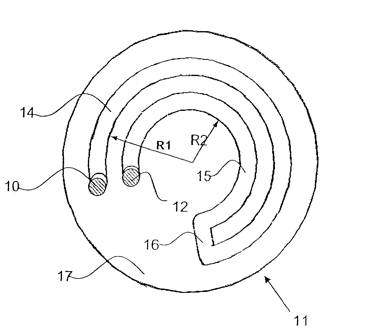
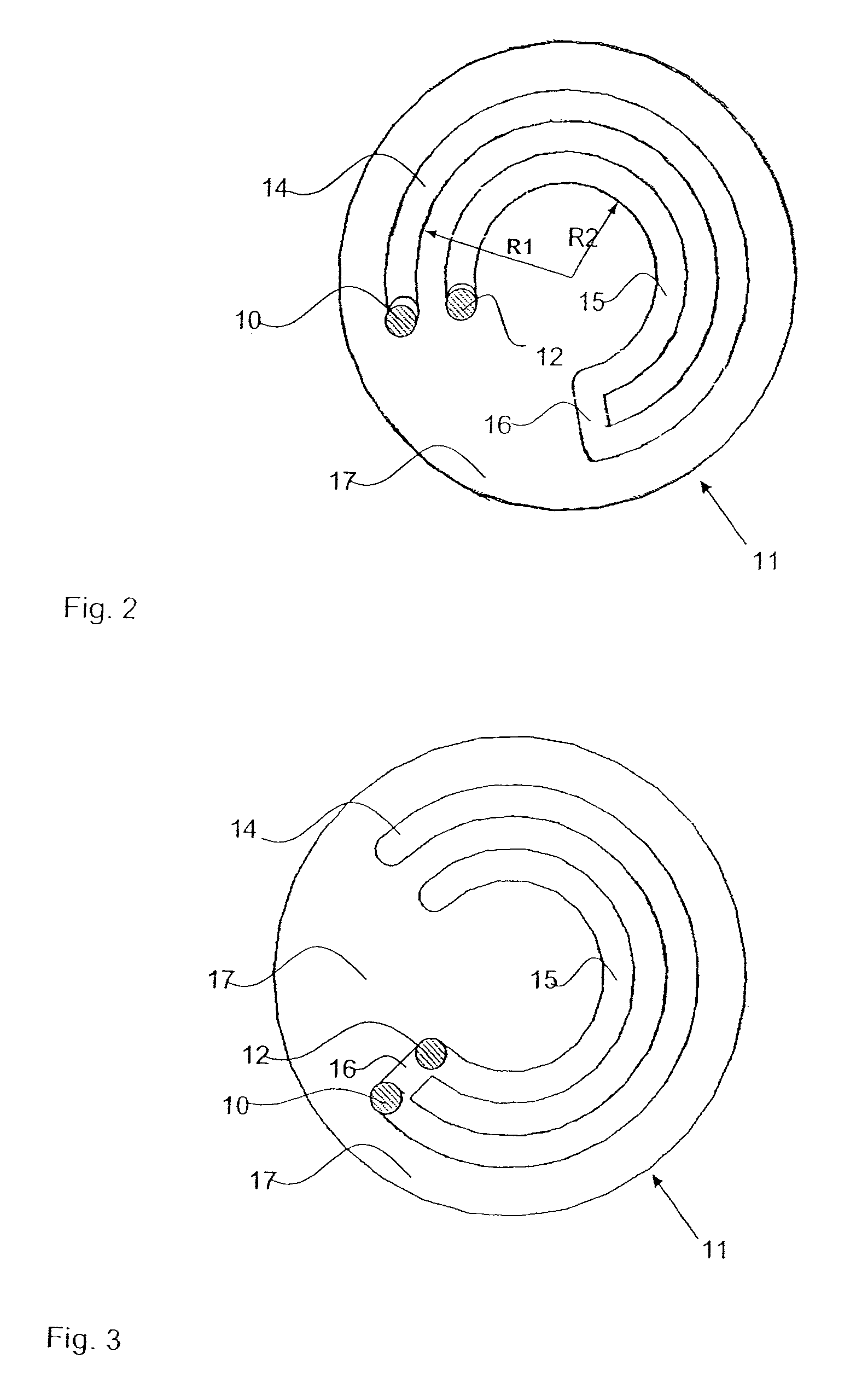
[0030]FIG. 2 schematically shows the design of a dispensing element 11 according to the present invention, which has a first dispensing channel 14 and a second dispensing channel 15. The dispensing channels 14, 15 extend along circular paths with different radii R1 and R2 and are connected to one another by a connection channel 16. The dispensing channels 14, 15 are milled as grooves into the carrier plate 17.

[0031]The gas inlet 10 and the gas outlet 12 are arranged stationarily on a housing, not shown more specifically, and the gas flow is from the gas inlet 10 to the gas outlet 12 via the first dispensing channel 14, the connection channel 16 and the second dispensing channel 15. Depending on the setting of the carrier plate 17 in relation to the stationary gas inlet 10 and the gas outlet 12, the effective length of the dispensing channels 14, 15 through which flow takes place is increased or decreased. The flow resistances of the bypass resistance 6 and of the dispensing channels...

second embodiment

[0033]FIG. 4 schematically shows the design of a dispensing element 111 according to the present invention with a third dispensing channel 18 and with a fourth dispensing channel 19 on a carrier plate 20. The two dispensing channels 18, 19 are connected to one another in terms of flow by means of a displaceable / rotatable connection channel 21 on a second carrier plate 26, which is shown only schematically. The third dispensing channel 18 is designed as a circular ring-shaped channel, at least on part of the circumference, and without contour or without an essential resistance in relation to dispensing. The fourth dispensing channel 19 has a cross-sectional area that extends over an angle of up to 340°.

[0034]The carrier plate 26 with the connection channel 21 can be pivoted by means of a setting wheel 25 along the arrow 22 and it now changes the position of the parts of the dispensing channels through which flow takes place. The gas flow through the second dispensing element 111 take...

third embodiment

[0035]FIG. 5 schematically shows the design of a dispensing element 112 according to the present invention with the third dispensing channel 18 and the fourth dispensing channel 19 on a carrier plate 20. The third dispensing channel 18 is degenerated, compared to FIG. 4, from a circular groove into a hole near the center. The fourth dispensing channel 19 and the carrier plate 26 with the connection channel 21 are designed corresponding to FIG. 4.


PUM

PropertyMeasurementUnit
cross-sectional areaaaaaaaaaaa
areaaaaaaaaaaa

Abstract

A dispensing element of an anesthetic vaporizer is provided that can be manufactured in a simple manner and makes it possible to dispense anesthetic over a broad setting range. The dispensing element (11) includes two, longitudinally extending dispensing channels (14, 15), which are connected to one another in terms of flow by means of a connection channel (16). The gas flows from one of the dispensing channels (14) into the other dispensing channel (15) via the connection channel (16).

Description

CROSS REFERENCE TO RELATED APPLICATIONS[0001]This application claims the benefit of priority under 35 U.S.C. §119 of German Patent Application DE 10 2006 044 099.4 filed Sep. 20, 2006, the entire contents of which are incorporated herein by reference.FIELD OF THE INVENTION[0002]The present invention pertains to an anesthetic vaporizer with an evaporator chamber for enriching parts of a fresh gas with anesthetic vapor and with a dispensing element with a gas inlet and with a gas outlet for introducing anesthetic vapor into a gas channel and with a setting means at the dispensing element.[0003]An anesthetic vaporizer of the type mentioned in the form of an anesthetic evaporator became known from DE-PS 12 71 903.BACKGROUND OF THE INVENTION[0004]In the prior-art anesthetic vaporizer, the gas flow is split into a bypass gas flow and an evaporator chamber gas flow after a gas inlet opening. The bypass gas flow flows via a bypass resistance to the outlet. The evaporator chamber gas flow is...

Claims


Application Information

Patent Timeline
Patent Type & Authority Patents(United States)
IPC IPC(8): B01F3/04B01F23/10
CPCA61M16/18B01F3/022B01F5/0498Y10S261/65B01F23/12B01F25/32
Inventor REICHERT, DIRK-STEFANGIPPERT, KARL-LUDWIGLUTTER, THOMAS
Owner DRAGERWERK AG
Why Eureka
Try Eureka