Replacement heart valve, valve holder and methods of making and using same

a heart valve and valve holder technology, applied in the field of replacement heart valves, can solve the problems of increased workload placed on the heart, stenosis and insufficiency, and emergency surgery, and achieve the effects of improving the workload of the heart valve, reducing the workload, and improving the patient's comfor

Active Publication Date: 2011-08-16
SAINT JOSEPHS TRANSLATIONAL RES INST +1
View PDF7 Cites 43 Cited by
  • Summary
  • Abstract
  • Description
  • Claims
  • Application Information

AI Technical Summary

Problems solved by technology

Congenital valve abnormalities may be well-tolerated for many years only to develop a life-threatening problem in an elderly patient, or may be so severe that emergency surgery is required within the first few hours of life.
Stenosis and insufficiency may occur concomitantly in the same valve or in different valves.
Both of these abnormalities increase the workload placed on the heart.
However, the currently available options cannot duplicate the advantages of native (natural) heart valves.
Some of the available mechanical valves tend to be very durable, but are problematic in that they are thrombogenic and exhibit relatively poor hemodynamic properties.
Some of the available artificial tissue valves may have relatively low thrombogenicity, but lack durability.
Additionally, even these artificial tissue valves often do not exhibit hemodynamic properties that approach the advantageous hemodynamic performance of a native valve.
Such artificial tissue valves still fall short in durability and in hemodynamic performance.
Although the immediate and long-term survival of patients is gratifying, all conduits deteriorate, requiring the need to have close, constant follow-up.
In the case of children, multiple surgeries are often required, which put the child at risk and can be physically and emotionally draining for the child and his or her family.
Therefore, a heretofore unaddressed need still exists in the art to address the aforementioned deficiencies and inadequacies.

Method used


Image

  • Replacement heart valve, valve holder and methods of making and using same
  • Replacement heart valve, valve holder and methods of making and using same
  • Replacement heart valve, valve holder and methods of making and using same

Examples


Embodiment Construction

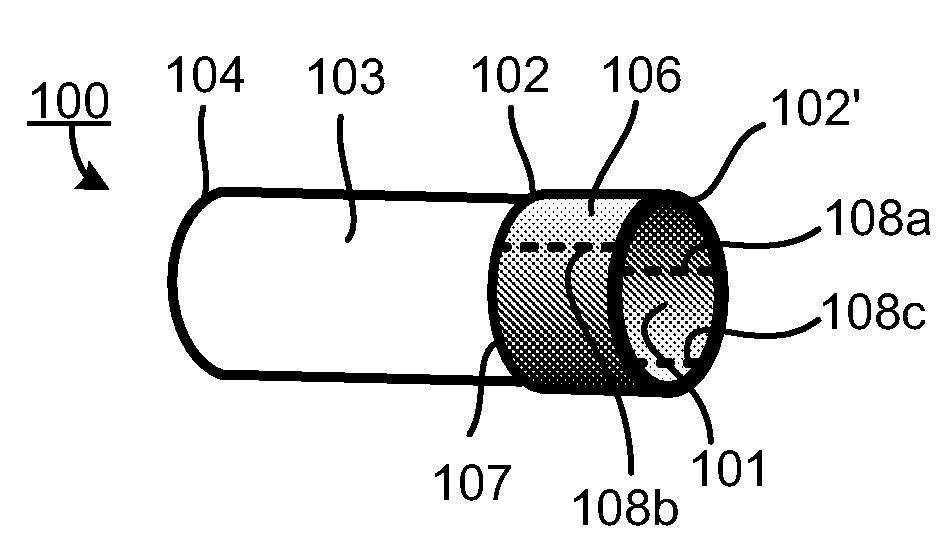
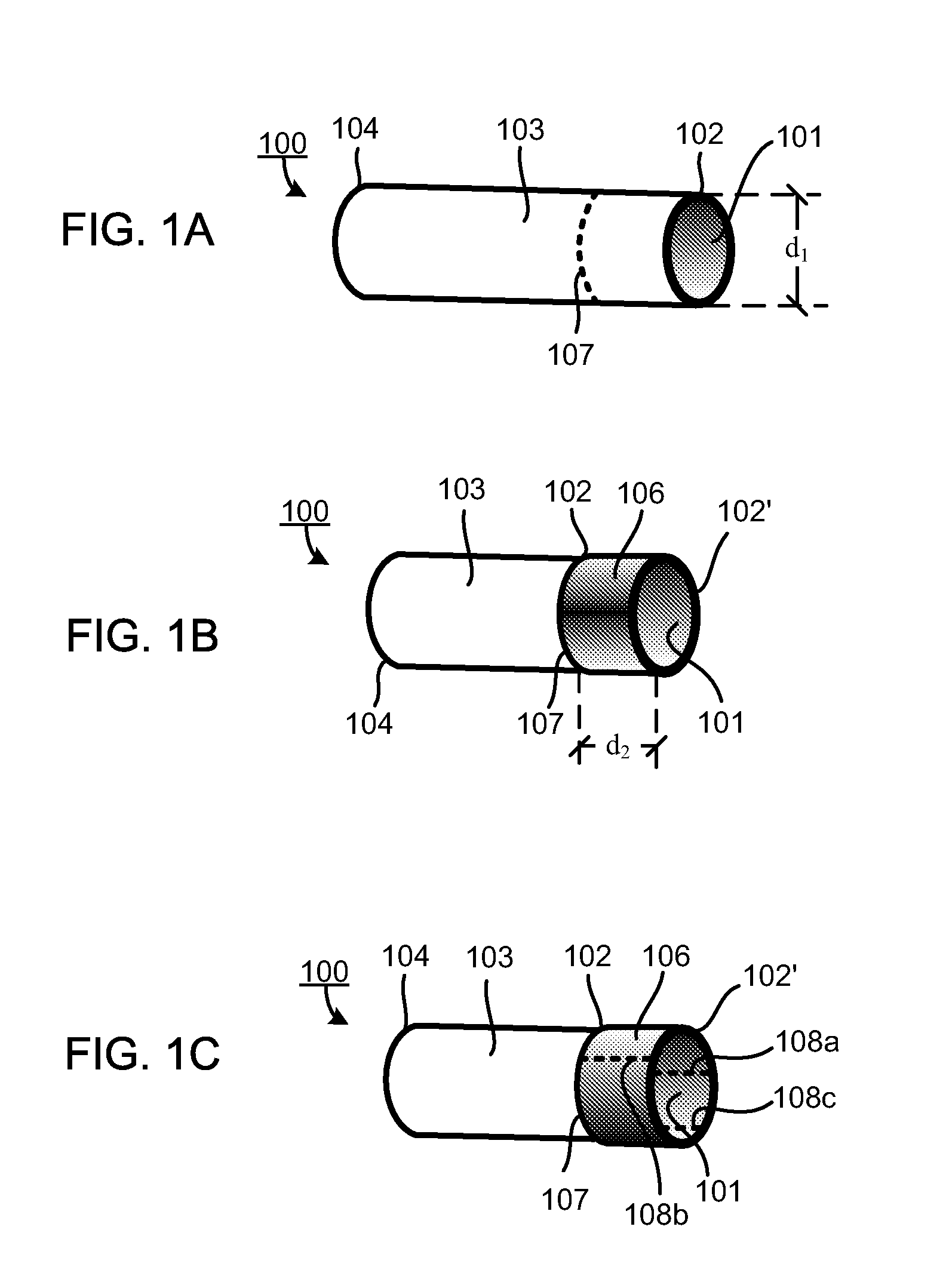
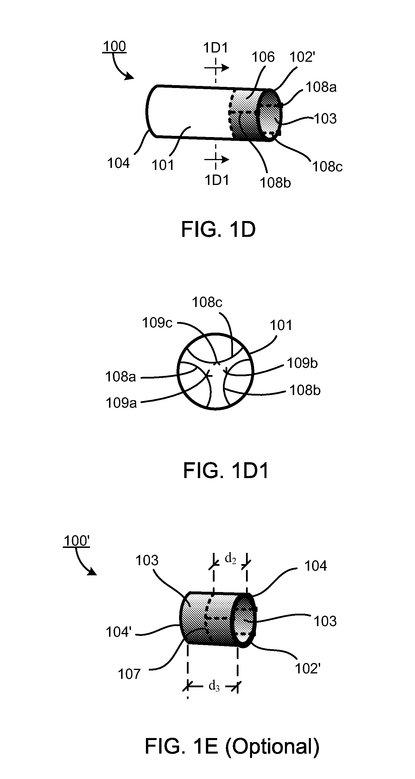
[0050]The present invention is more particularly described in the following examples that are intended as illustrative only since numerous modifications and variations therein will be apparent to those skilled in the art. Various embodiments of the invention are now described in detail. Referring to the drawings, like numbers indicate like components throughout the views. As used in the description herein and throughout the claims that follow, the meaning of “a”, “an”, and “the” includes plural reference unless the context clearly dictates otherwise. Also, as used in the description herein and throughout the claims that follow, the meaning of “in” includes “in” and “on” unless the context clearly dictates otherwise. Additionally, some terms used in this specification are more specifically defined below.

[0051]As used herein, “around”, “about” or “approximately” shall generally mean within 20 percent, preferably within 10 percent, and more preferably within 5 percent of a given value ...


PUM

PropertyMeasurementUnit
diameteraaaaaaaaaa
diameteraaaaaaaaaa
volumeaaaaaaaaaa

Abstract

A replacement heart valve device usable in a medical procedure in relation in heart valve replacement of a patient. In one embodiment, the replacement heart valve device includes a heart valve holder or conduit holder formed in the form of a cylindrical tube having a longitudinal cut substantially extending from one end to the other end of the cylindrical tube, and a conduit formed with a tubular segment of an elastic material. The conduit is mountable onto the heart valve holder or conduit holder or self-expanding stent. In one embodiment, at least a portion of the conduit is formed with a single layer of the elastic material. In another embodiment, at least a portion of the conduit is formed with two layers of the elastic material.

Description

CROSS-REFERENCE TO RELATED PATENT APPLICATION[0001]This application claims the benefit, pursuant to 35 U.S.C. §119(e), of U.S. provisional patent application Ser. No. 60 / 925,822, filed Apr. 23, 2007, entitled “REPLACEMENT HEART VALVE, VALVE HOLDER AND METHODS OF MAKING AND USING SAME,” by Megumi Mathison, which is incorporated herein by reference in its entirety.FIELD OF THE INVENTION[0002]This invention relates to a replacement heart valve, and more particularly relates to a replacement heart valve formed with a tubular segment of an elastic material for replacement of a defective heart valve of a human or animal.BACKGROUND OF THE INVENTION[0003]There are four valves in the heart that serve to direct blood flow through the two sides of the heart. On the left (systemic) side of the heart are: (1) the mitral valve, located between the left atrium and the left ventricle, and (2) the aortic valve, located between the left ventricle and the aorta. These two heart valves direct oxygenate...

Claims


Application Information

Patent Timeline
Patent Type & Authority Patents(United States)
IPC IPC(8): A61F2/06
CPCA61F2/2412A61F2/2415Y10T29/49405A61F2240/001
Inventor MATHISON, MEGUMI
Owner SAINT JOSEPHS TRANSLATIONAL RES INST
Why Eureka
Try Eureka