

Display apparatus
a technology for display devices and display cases, applied in the field of display devices, to achieve the effect of reducing the volume of packaging
- Summary
- Abstract
- Description
- Claims
- Application Information
AI Technical Summary
Benefits of technology
Problems solved by technology
Method used
Image

Examples
Embodiment Construction
[0036]Reference will now be made in detail to the embodiments of the present general inventive concept, examples of which are illustrated in the accompanying drawings, wherein like reference numerals refer to like elements throughout. The embodiments are described below in order to explain the present general inventive concept by referring to the figures.
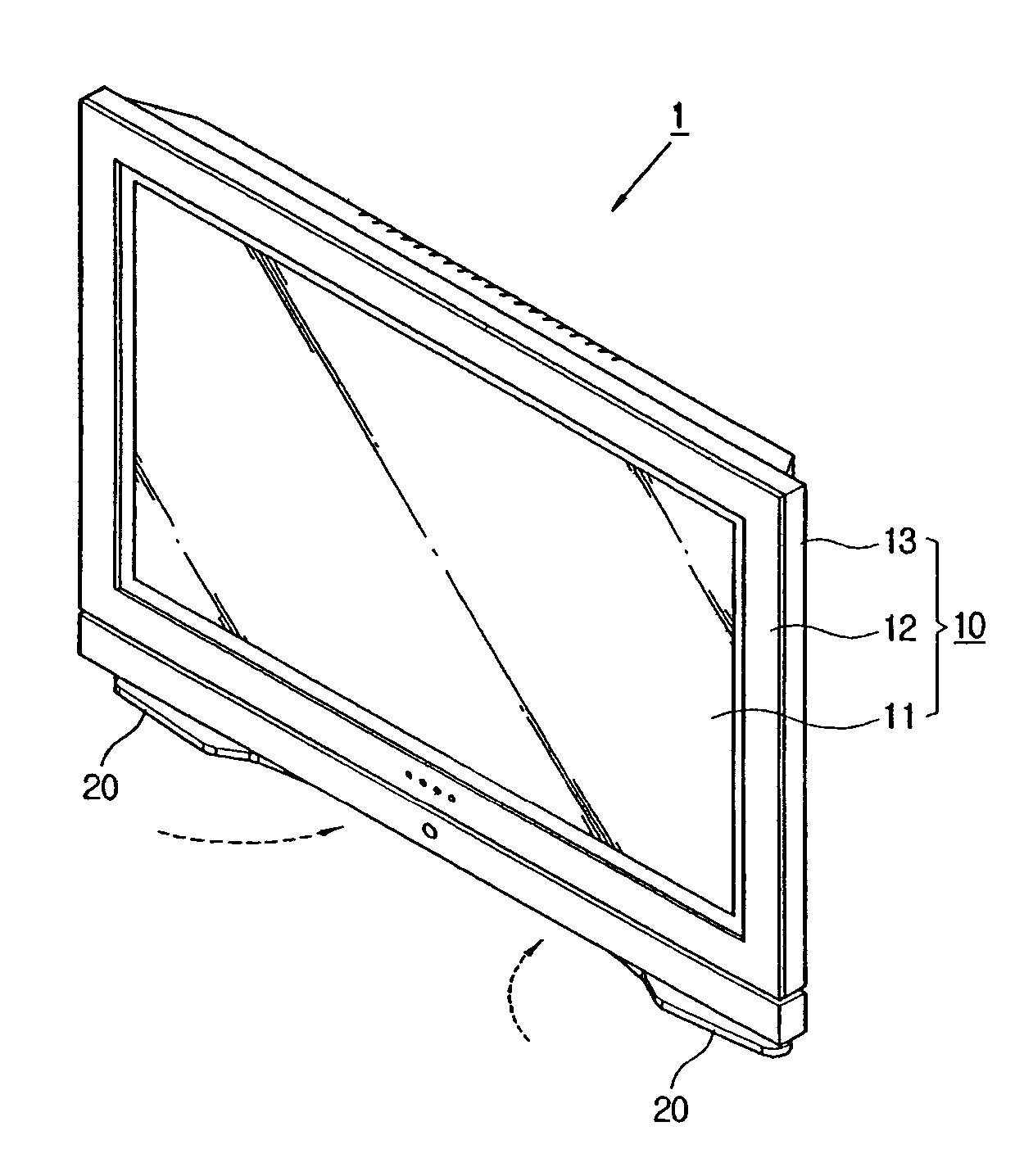
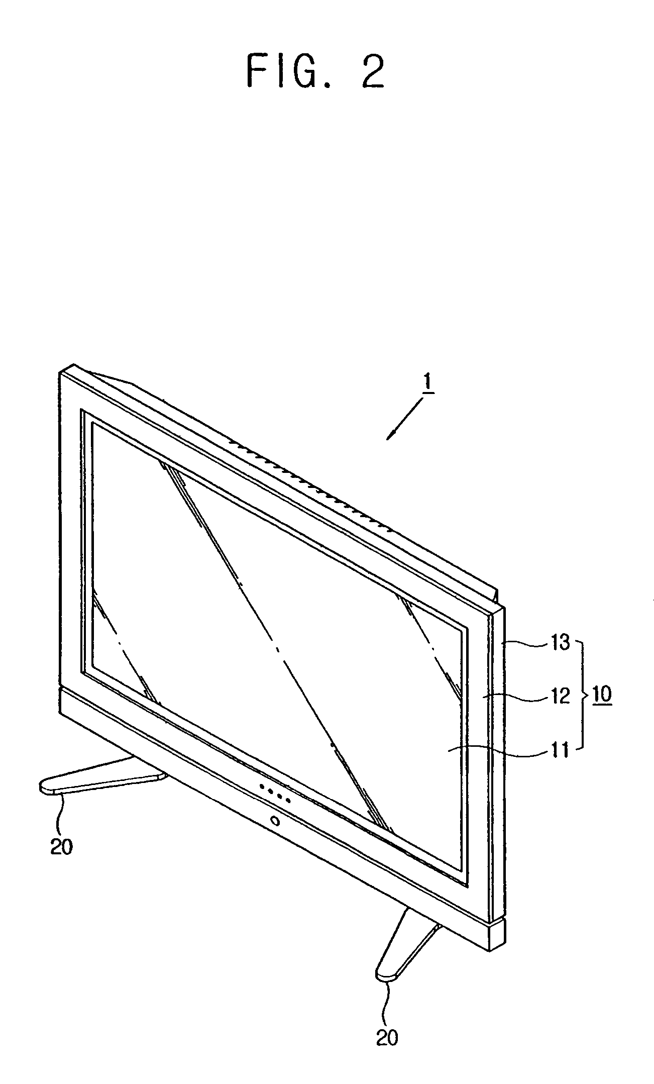
[0037]FIG. 2 is a perspective view illustrating a display apparatus 1 according to an embodiment of the present general inventive concept. FIGS. 3 and 4 are partial exploded perspective views illustrating the display apparatus 1 of FIG. 2. FIG. 5 is an exploded perspective view illustrating bases 20 and supporters 30 of the display apparatus 1 of FIG. 2. Referring to FIGS. 2 through 5, the display apparatus 1 comprises a display 10 which displays an image on a major display screen thereof, and the bases 20 which are coupled to the display 10 to rotate around an axis of upward and downward directions with respect to the display 10. F...
PUM
 Abstract
Description
Claims
Application Information