
Fin retention and deployment mechanism

a technology of fins and deployment mechanisms, applied in the field of fin retention and deployment mechanisms, can solve the problems of cost and required bearing

Active Publication Date: 2009-01-13
GEN DYNAMICS ORDNANCE & TACTICAL SYST
View PDF40 Cites 18 Cited by
  • Summary
  • Abstract
  • Description
  • Claims
  • Application Information

AI Technical Summary

Benefits of technology

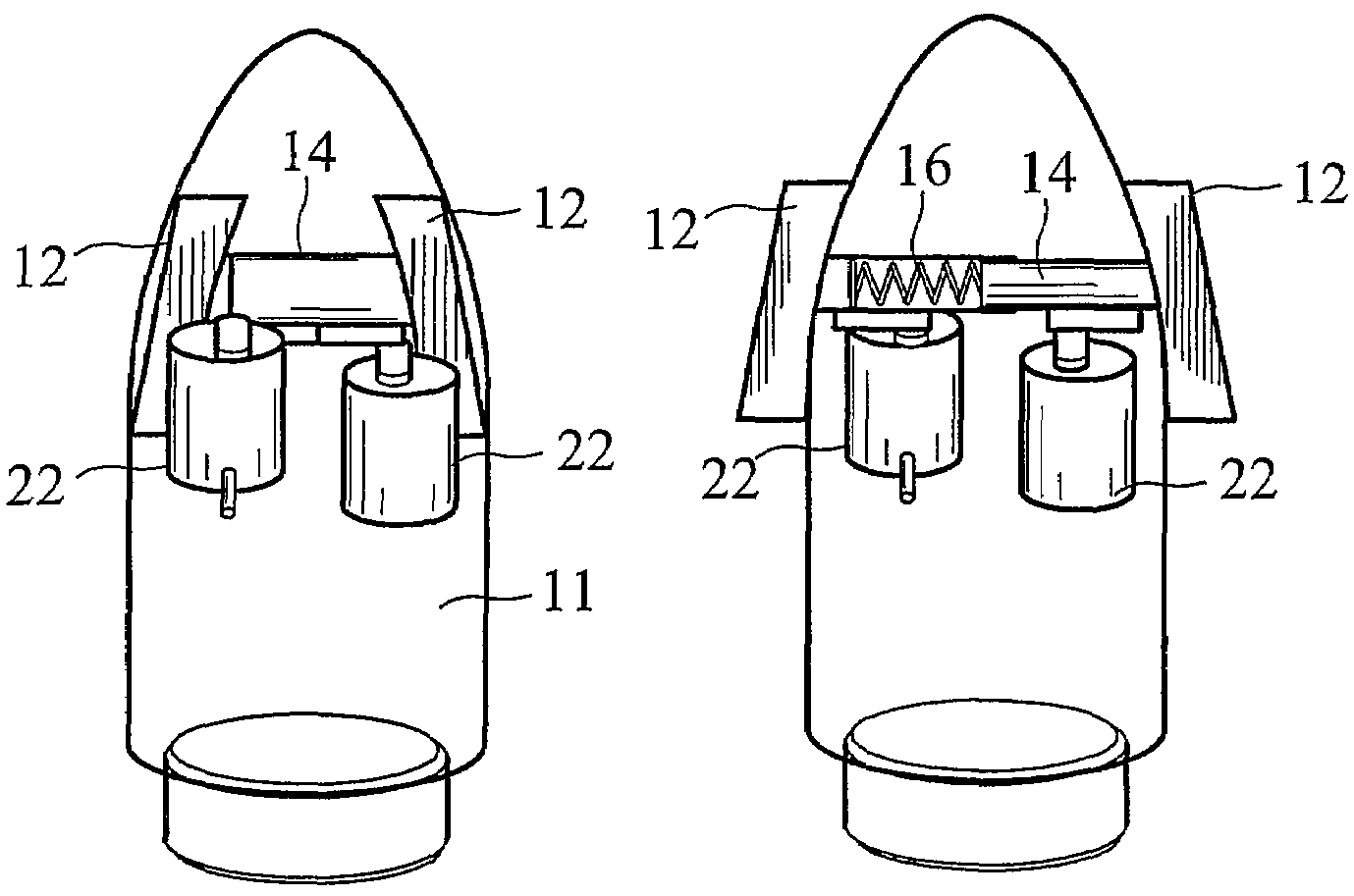
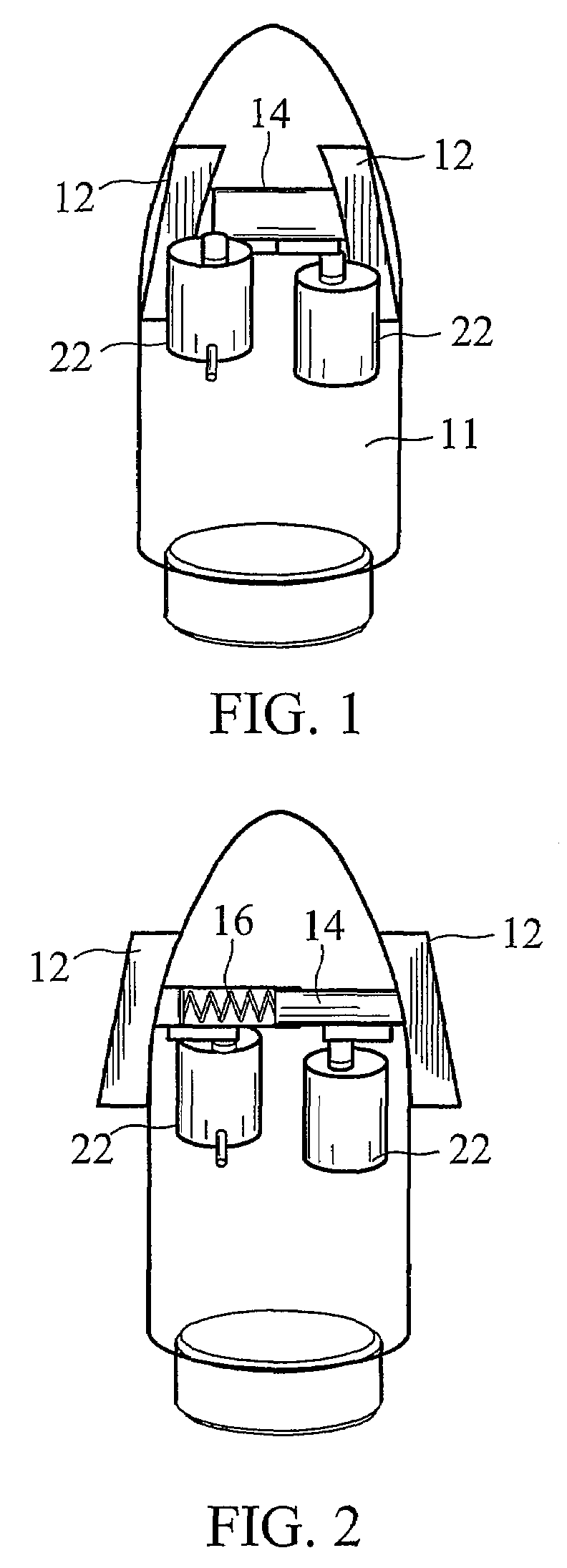
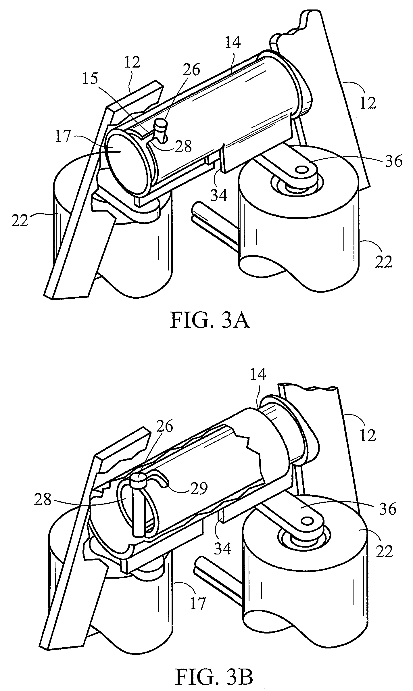
"The fin retention and deployment mechanism described in this patent allows for the deployment of aerodynamic control surfaces on command without the need for an additional actuation device or control circuitry separate from the actuator that controls the angle of the fins during flight. The actuator that is already required for operation of the control surfaces after deployment initiates the deployment of the fins, as well. The mechanism also eliminates the need for a separate cover to retain the fins, reducing cost and complexity. The fins are retained in the stowed position by a latching mechanism, and any coupling of an actuator used for controlling the fins during flight that allows for relative rotational motion of a retaining member and a latch in a shaft may be used to free the retaining member from the latch. Once deployed, the fins may be attached to the shaft or fixed relative to the shaft by a latch and retaining member or any other locking or fixation element such that the fins rotate about the shaft axis with the shaft."

Problems solved by technology

These bearing are costly, but required, due to the inherently short lengths of the shaft protruding into the projectile body of most known systems.
Thus, the use of bearings is optional and costly bearings may be replaced by ordinary bushings or a slip fit between the shaft and housing support.

Method used


Image

  • Fin retention and deployment mechanism
  • Fin retention and deployment mechanism
  • Fin retention and deployment mechanism

Examples


Embodiment Construction

[0014]This detailed description and drawings provide specific examples of the invention, but the invention should not be limited merely to the examples disclosed. Instead, the invention should be limited only by the claims that may eventually issue. Many variations in the system, changes in specific components of the system and uses of the system will be readily apparent to those familiar with the field based on the drawings and description provided.

[0015]As used herein, the term “projectile” refers to any launched object regardless of the object's purpose or method of propulsion. This description generally utilizes gun-launched projectiles as an appropriate example of the invention. However, other potential projectiles are contemplated and would be obvious to one of ordinary skill in the art. Examples include, but are not limited to, missiles, rockets, torpedoes, shells, rounds, and bullets.

[0016]As used in this application the term “fin” refers to any projection extending from the...


PUM


Abstract

A fin retention and deployment mechanism that has the advantage of providing for the deployment of aerodynamic control surfaces on command without the need for an additional actuation device or control circuitry separate from the actuator that controls the angle of the fins during flight. The actuator that is already required for operation of the control surfaces after deployment initiates the deployment of the fins, as well. A latch mechanism comprises a retaining member and a lath, which engages the retaining member enabling a biasing mechanism to force the fins from a stowed position to a fully deployed position.

Description

FIELD OF THE INVENTION[0001]The field relates to deployment mechanisms for fins used in directional control of guided projectiles.BACKGROUND[0002]Existing actuators for fin control on gun-launched projectiles are known, but are both complex and expensive. The requirement to withstand the acceleration forces, which typically range from 10,000 to 30,000 times the force of gravity, places very stringent demands on the actuators. Therefore, the designs are required to be extremely robust in order to withstand the loads induced by these accelerations. Existing actuators for fin control on gun-launched projectiles typically employ electric motors to drive the fins through a gear reduction system. These motors are either brush or brushless types that make several revolutions of the motor while moving the fin from one travel limit to the other. In the case of the brush type motors, there are substantial reliability issues with the brush systems due to the high acceleration loads and problem...

Claims


Application Information

Patent Timeline
Patent Type & Authority Patents(United States)
IPC IPC(8): F42B10/64
CPCF42B10/14F42B10/64
Inventor SCHROEDER, RICHARD W.
Owner GEN DYNAMICS ORDNANCE & TACTICAL SYST
Learn More