Shaft joint

a technology of shaft joint and shaft, which is applied in the direction of wing accessories, couplings, rod connections, etc., can solve the problems of large system size, cumbersome and difficult to load such items into the car, and the whole carton can prove unwieldy for many peopl

Inactive Publication Date: 2011-08-23
THE CHAMBERLAIN GRP INC
View PDF48 Cites 13 Cited by
  • Summary
  • Abstract
  • Description
  • Claims
  • Application Information

AI Technical Summary

Problems solved by technology

One of the issues presented with transporting the operator system to the installation site is the size of the system.
Though some people have uncommonly large automobiles or other vehicles that may provide for a shaft having an eight-foot length, many people find it cumbersome and difficult to load such an item into their car.
Were the rail and shaft a single component of eighty or more inches, and this were packaged in a single carton with a relatively heavy operator box, the entire carton can prove unwieldy for many people.

Method used


Image

  • Shaft joint
  • Shaft joint
  • Shaft joint

Examples


Embodiment Construction

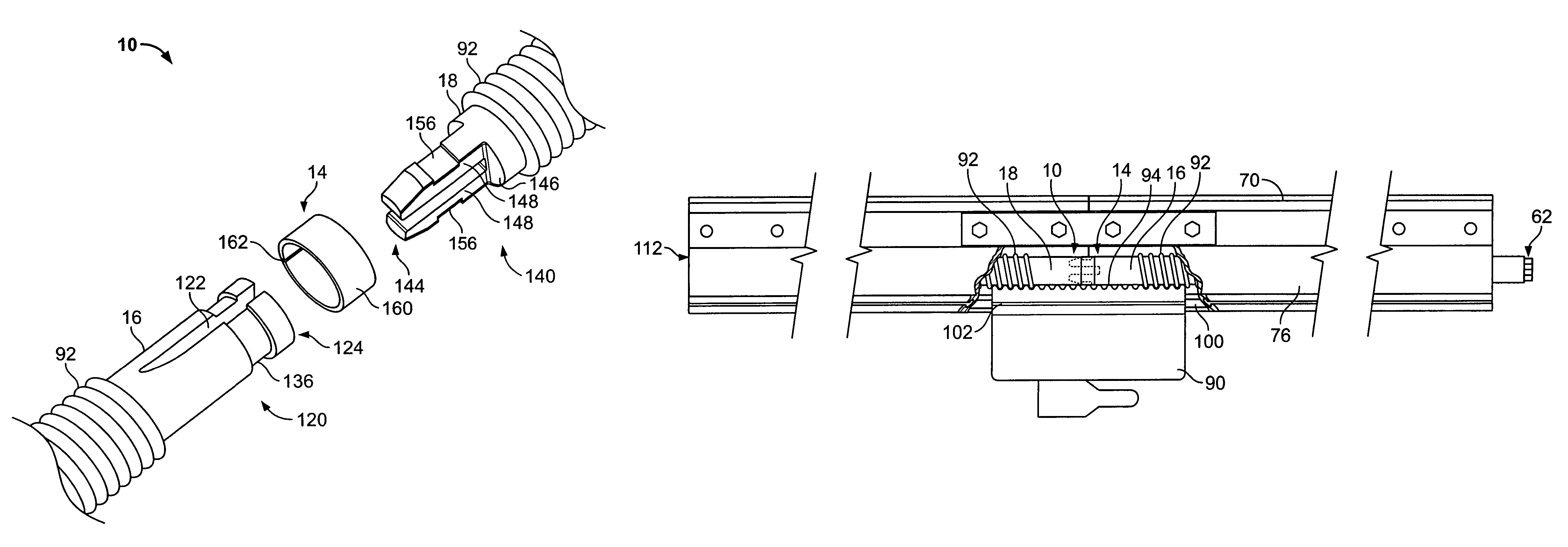
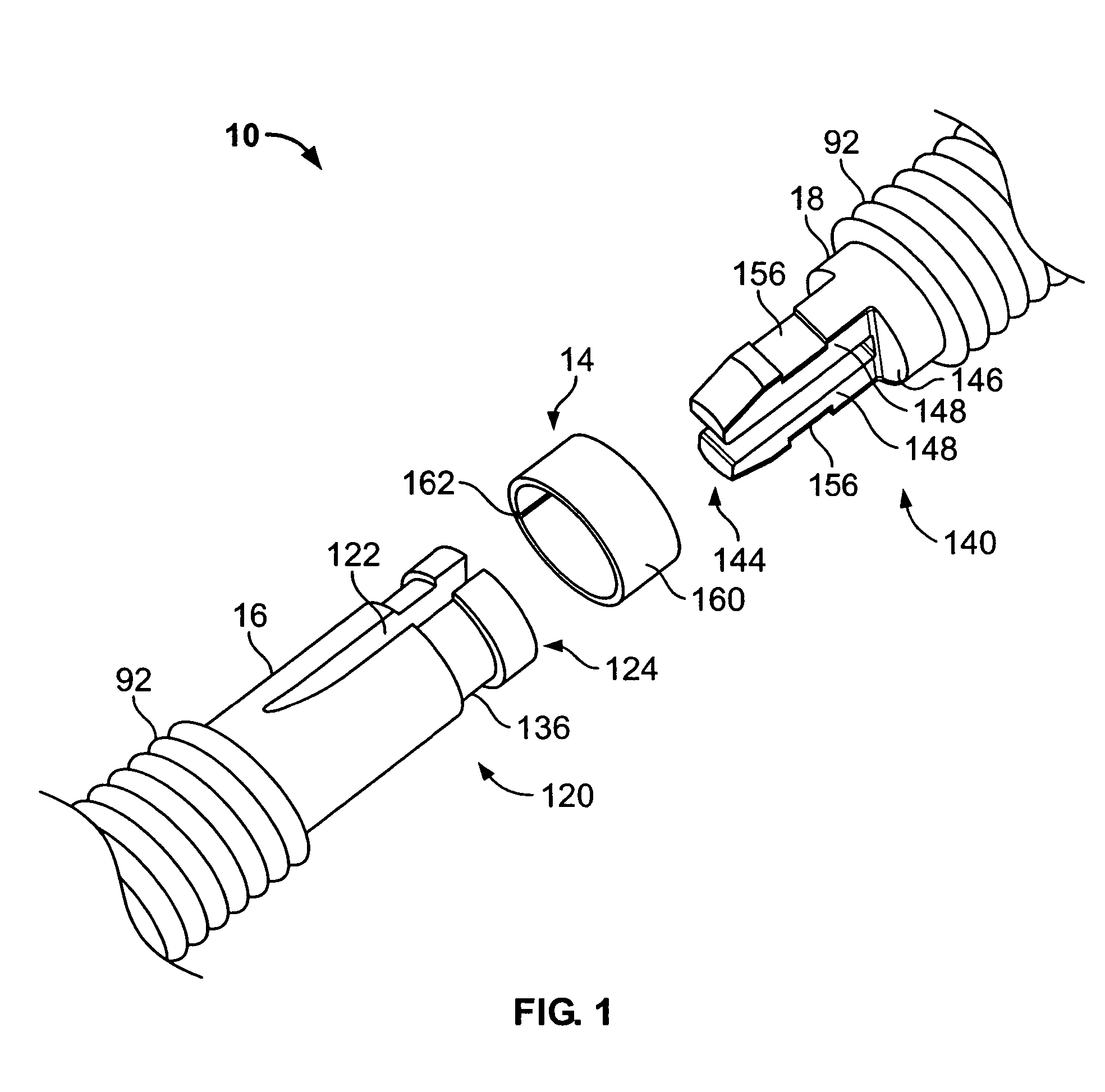
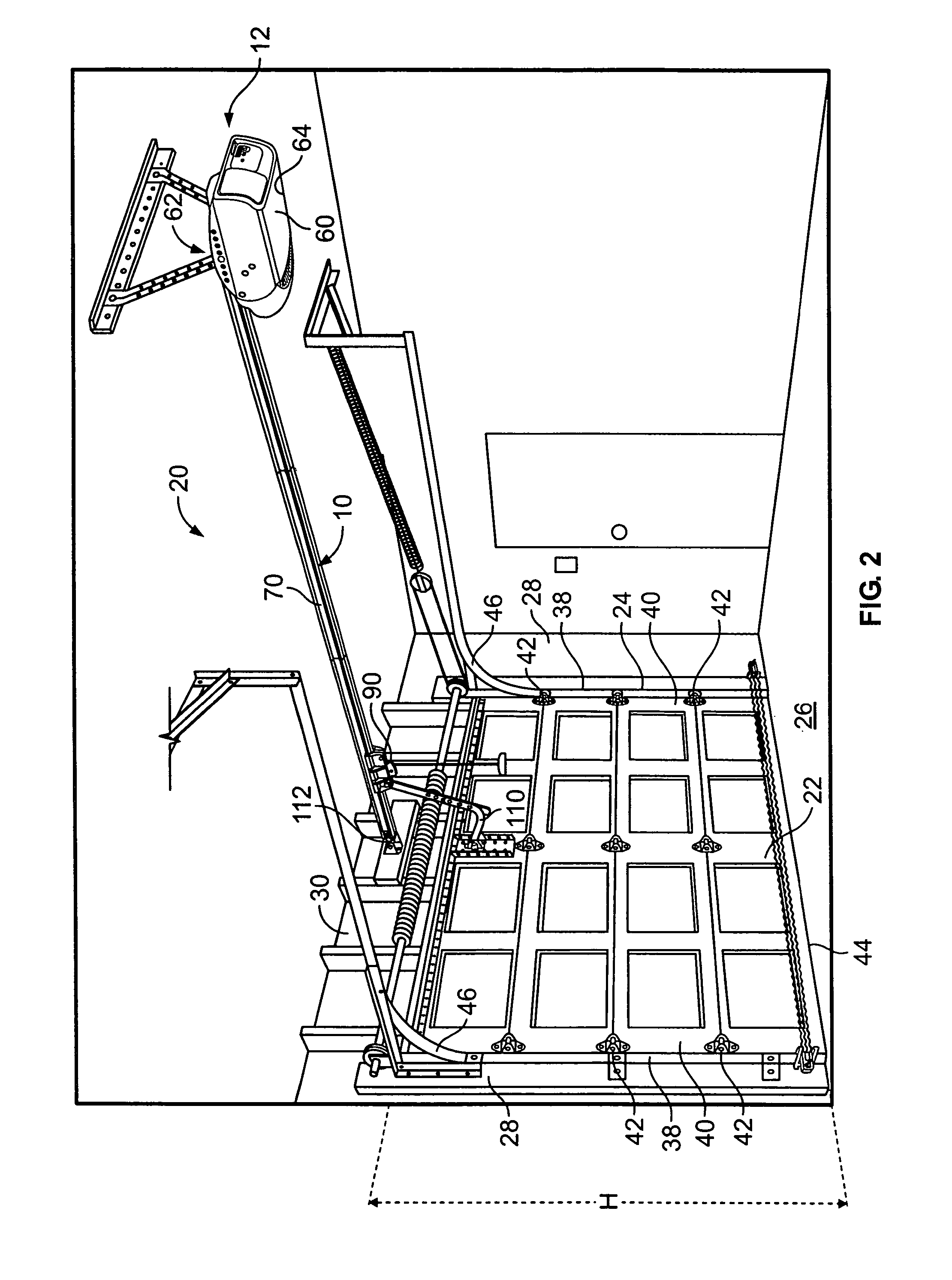
[0028]Referring initially to FIGS. 1 and 2, a rotating shaft 10 for use with a operator system 12 for moving a movable barrier 22 between positions defining open and closed positions for a garage 20 is depicted. The rotating shaft 10 forms a connection joint 14 between first and second shaft segments 16, 18. The garage 20 includes an opening 24 generally bound by a ground or floor surface 26, side walls 28, and a top wall 30. FIG. 2 illustrates the garage 20 with the barrier 22 in a closed position such that the opening 24 is generally spanned by the barrier 22. The operator system 12 is used to raise the barrier 22 from the closed position to an open position to allow ingress and egress of persons, vehicles, or the like, through the opening 24.

[0029]The barrier 22 is guided between the open and closed positions by rails or tracks 38 mounted to the side walls 28. The barrier has sides 40 which include axle and wheel assemblies 42. The wheel assemblies 42 are positioned within the tr...


PUM


Abstract

A shaft such as a worm drive shaft for a movable barrier operator is disclosed. The shaft includes at least two shaft segments having connection ends. The shaft segments include respective connection ends permitting a first connection end to be joined with a second connection end by inserting a portion of at least one of the connection ends within the other connection end along the longitudinal axis of the shaft. The shaft segments may be retained by a resiliently expandable connector such as a snap ring. The connector may expand to permit the joining and then contract to be received within a surface recess on a connection end. The connector may be part of or pre-assembled on a connection end, such as by being positioned within a surface recess thereof. The connector may provide a pre-determined position for joining the first and second connection ends.

Description

FIELD OF THE INVENTION[0001]The invention relates to a connection between elongated members and, in particular, to a connection between sections or segments of a drive shaft for a movable barrier operator.BACKGROUND OF THE INVENTION[0002]Many residential garages are equipped with an operator for providing electromechanical movement of the garage door between an open position and a closed position. Various systems have been devised for attaching the operator to the garage door to effect such movement. These systems may include a cable, a belt, or a threaded shaft commonly referred to as a worm shaft.[0003]For many residential owners, the installation of a garage door seems a relatively easy, do-it-yourself task. Instruction manuals are presented with detailed pictures and precautions to guide people through the steps, necessitating equipment as common as a screwdriver and a power drill. Before beginning installation, however, the would-be installer must first acquire or purchase the ...

Claims


Application Information

Patent Timeline
Patent Type & Authority Patents(United States)
IPC IPC(8): E05F11/00
CPCF16D1/02E05F15/673F16D1/116E05Y2201/702E05Y2800/205E05Y2800/696E05Y2900/106F16B7/0426Y10T403/7045Y10T403/7016Y10T403/551Y10T403/606Y10T403/66Y10T403/535E05Y2201/706F16B7/0406
Inventor LHOTAK, ROGER W.
Owner THE CHAMBERLAIN GRP INC
Why Eureka
Try Eureka