Laying head with a vibration damping device

a technology of vibration damping and laying head, which is applied in the direction of bearings, dynamo-electric machines, roller bearings, etc., can solve the problems of vibration that increases in intensity, components are no longer dynamically balanced, and high vibration

Active Publication Date: 2011-08-23
DANIELI & C OFF MEC SPA
View PDF13 Cites 7 Cited by
  • Summary
  • Abstract
  • Description
  • Claims
  • Application Information

AI Technical Summary

Benefits of technology

[0013]Therefore, the main object of the present invention is to produce a laying head that can operate at a rolling speed of over 120 m / sec up to at least 140 m / sec without being affected by harmful vibrations caused by dynamic amplification phenomena.
[0014]The invention must also allow this scope to be achieved at acceptable engineering costs, without mechanically complicating the devices and without giving rise to severe wear conditions of the mechanical elements.

Problems solved by technology

In a laying head, as a result of the pipe wear during operation, it inevitably occurs that the rotating components are no longer dynamically balanced, thus causing vibrations that increase in intensity as the rotation speed increases.
These dynamic amplifications produce high vibrations which are detrimental to structural integrity, and in fact limit the maximum operating speeds which can be reached.
This type of support is composed of rollers radially arranged with respect to the shaft but this device is very complicated in mechanical terms and has low efficiency, since also the rollers are provided with their own flexibility.
Having small diameters, the rollers are subjected to extremely high rotational speeds.
Another drawback of this solution consists in the fact that even minimum differences in coaxiality between the end bearings and the additional support cause unacceptable vibrations in the system.
A drawback of this type of device is its high cost.
In this way some clearances and the relative vibrations are partly reduced, but the solution is not very practical and optimal results cannot be obtained.
It is known that mechanical rolling bearings with such large dimensions become particularly critical at high rotation speeds, and therefore this solution is not very practical and, moreover, frequent breakage of these mechanical bearings occurs.

Method used


Image

  • Laying head with a vibration damping device
  • Laying head with a vibration damping device
  • Laying head with a vibration damping device

Examples


Embodiment Construction

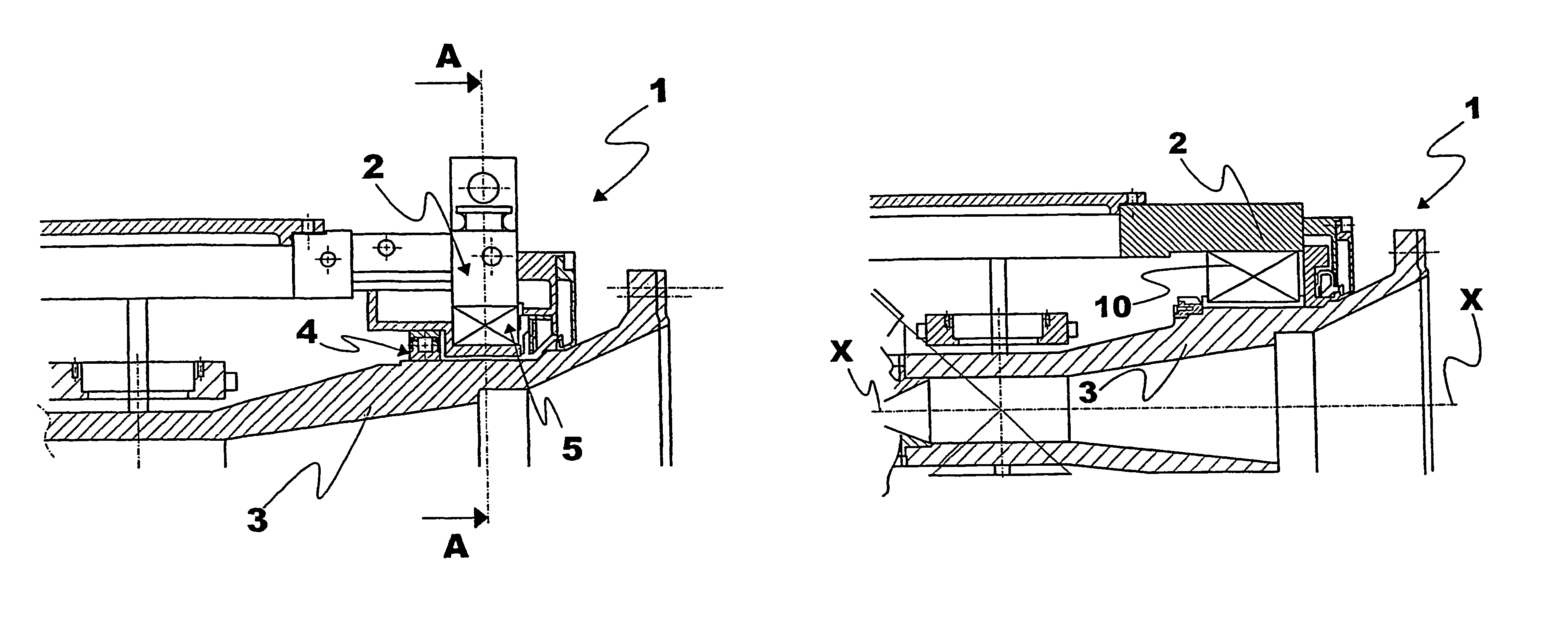
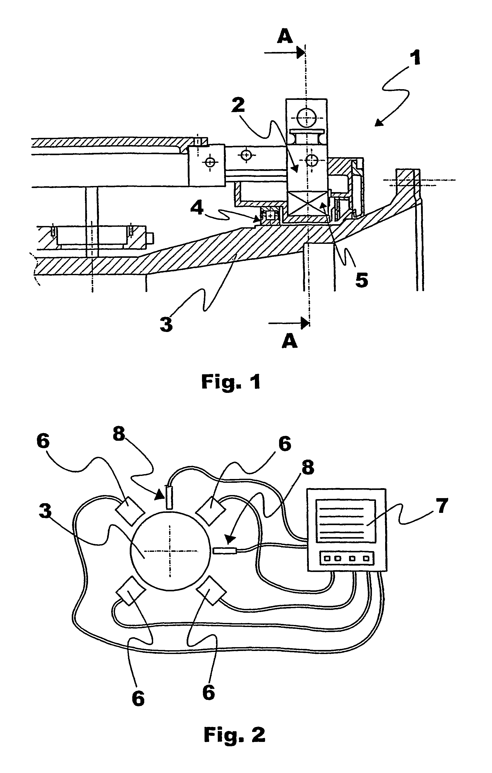
[0046]With particular reference to the cited figures, a laying head, indicated as a whole with the reference numeral 1, comprises a support structure 2, also called stator body, in which a rotor 3 is adapted to rotate about an own axis (X) and is held in rotation by means of two mechanical bearings 4, for example roller bearings. The rotor 3 substantially comprises a spindle housing the laying pipe, through which the rolled material to be coiled passes. On the rolled product inlet side in the rotor, the bearing has a smaller diameter and on the outlet side of the rotor the supporting mechanical bearing 4 has a larger diameter. One of the bearings, for example the one with the smaller diameter, not shown in the figure, performs a constraining function in the axial direction.

[0047]The rotor 3 is fixed integral to a conical wheel that receives motion by means of a gear train of a motor, not shown, of known type. Another device of known type can also be used as the driving mechanism.

[00...


PUM

PropertyMeasurementUnit
angular velocitiesaaaaaaaaaa
rotational speedsaaaaaaaaaa
diameteraaaaaaaaaa

Abstract

A laying head for forming coils using continuous and substantially rectilinear rolled products such as rods or wire, having vibration damping means integrated in one of two rotor supports (3), preferably the one on the rolled product outlet side. Said means comprise a plurality of coils (6, 6′, 6″) arranged around the rotor (3), rotating about its axis (X), which generate a magnetic field actively controlled by a computer, the resultant force of which is perpendicular to the axis (X) and of a predetermined intensity so as to eliminate the inertial forces generated by the mass imbalances. Alternatively, the damping means incorporated in one of the supports are comprised of oil film bearings.

Description

FIELD OF THE INVENTION[0001]The present invention relates to a laying head having a vibration damping device for winding of substantially rectilinear rolled steel products, such as wire, rods or the like.PRIOR ART[0002]A relatively common solution utilized in realizing laying heads consists in providing a rotor in which the laying pipe is housed. The rotor is supported as cantilever on a stator body by means of two roller bearings, or supports, and in turn the stator body is rigidly constrained to a base integral with the ground. The rotor rotates about its own axis, generally at high angular velocities, which reach 2200 rpm, corresponding to a rolling speed of 120 m / sec. Rotation is produced by an external motor connected by means of a bevel gear drive system. Some types of laying heads have rotors that integrate the motor within and mount the motor stator coaxially.[0003]In a laying head, as a result of the pipe wear during operation, it inevitably occurs that the rotating compone...

Claims


Application Information

Patent Timeline
Patent Type & Authority Patents(United States)
IPC IPC(8): H02K7/09B21C47/14F16C17/03
CPCB21C47/143
Inventor DE LUCA, ANDREAPOLONI, ALFREDOPAIARO, IVANZERAJIC, MIROSLAV
Owner DANIELI & C OFF MEC SPA
Why Eureka
Try Eureka