Prefabricated articulating pier cap

a technology of articulating piers and supports, which is applied in the direction of bridges, shafts and bearings, constructions, etc., can solve the problems of long construction time, high construction costs, and inflexible design of current prefabricated components, and achieve the effect of improving the support structur

Inactive Publication Date: 2011-08-30
BENNETT JEFFERY W
View PDF18 Cites 13 Cited by
  • Summary
  • Abstract
  • Description
  • Claims
  • Application Information

AI Technical Summary

Benefits of technology

[0015]Accordingly, it is an object of the present invention to provide an improved support structure for a transportation passageway.

Problems solved by technology

Under conventional methods, the highway interstate construction can be very disruptive to the traveling public.
This method results in long construction times since the various frameworks must be first built.
Current pre-fabricated components do not lend themselves to flexible designs.
These current designs lack the capability fore any substantive adjustment post manufacturing, including at the construction sight.
As such, the current pre-fabricated components require extensive planning during the early stages of the projects.
First, little to no adjustment can be made at the construction site if those measurements and specifications are wrong. As such, sections of those piers are sometimes wasted because they did not fall into the proper dimensions for the roadway being built. Additionally, given the precise nature of the construction of those piers, installation can be very tedious in order to properly position those prior art piers.
The second drawback to this sort of construction is the fact that each pier, bridge section, or overpass section must be individually constructed per the specifications for that particular section of transportation passageway.
As such, little if any mass production of the piers for the transportation passageway can be made in advance.

Method used


Image

  • Prefabricated articulating pier cap
  • Prefabricated articulating pier cap
  • Prefabricated articulating pier cap

Examples


Embodiment Construction

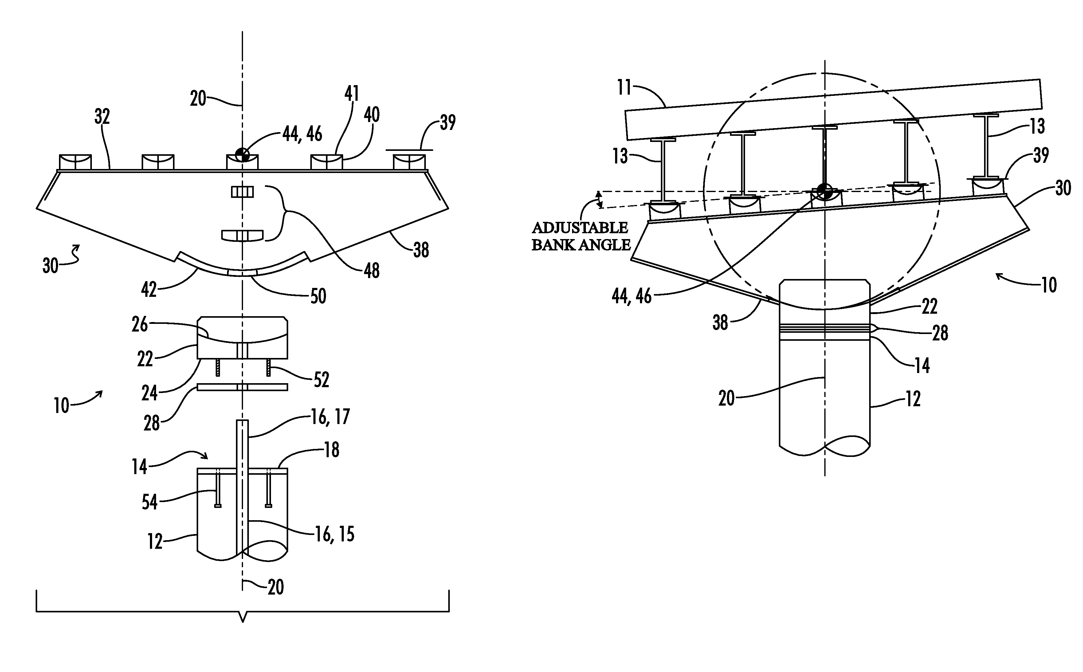
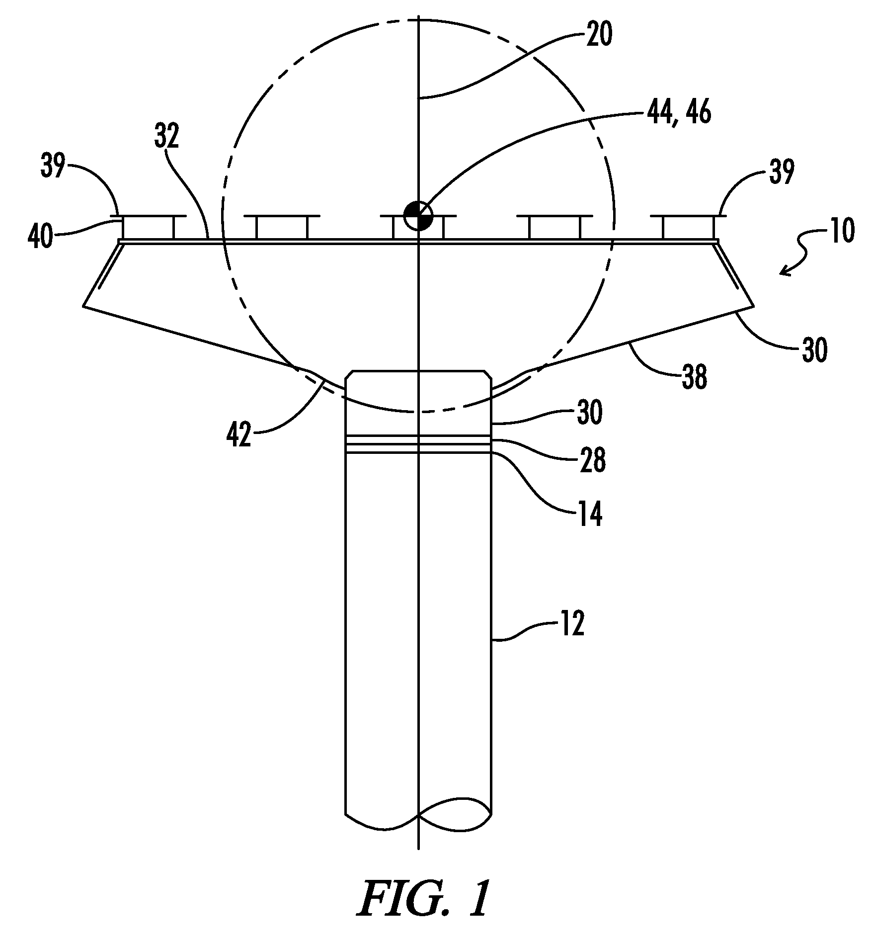
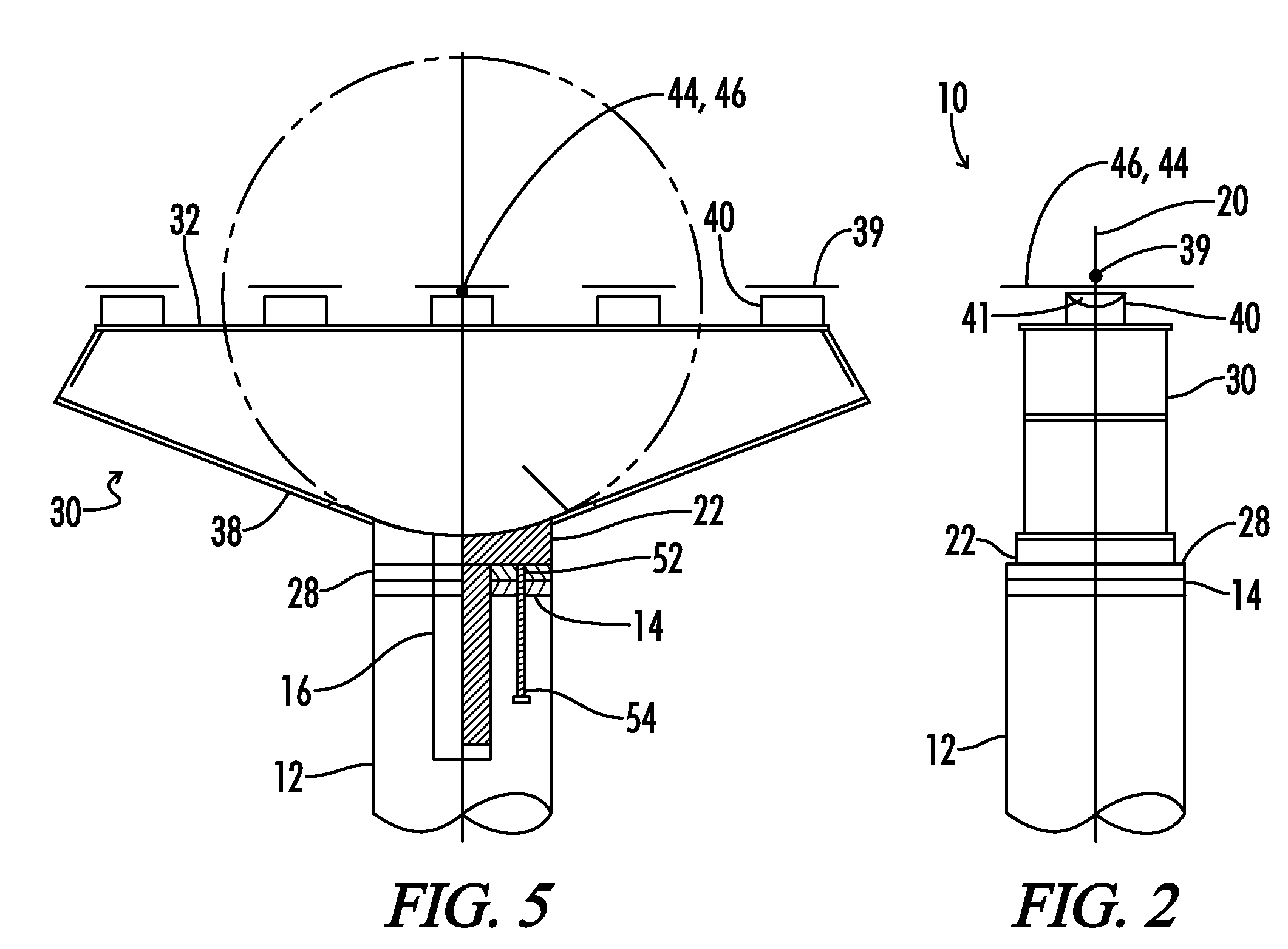
[0029]Referring now generally to the drawings, a support structure 10 for a transportation passageway 11 supported by column 12. The transportation passageway 11 can be various transportation passageways including, those passageways traveled by automobiles, trains, and the like. For example, the transportation passageway can be a bridge, overpass, on-ramp, exit ramp, viaduct, raised rail, and the like about which such items as vehicles, automobiles, trains, and the like traverse.

[0030]The support structure 10 comprises a bearing 14, bracket 22, and cap 30. The bearing 14 includes a post 16, which can also be described as a stanchion 16, having an anchor side 15. The bearing 14 includes a bracket face 18 and a bearing axis of rotation 20. The anchor 15 is shaped to fix the bearing 14 to the column 12. The anchor 15 can be positioned in a column 12 and the column 12 can be cast around the anchor 15 to secure the bearing 14 to the column 12.

[0031]The bracket 22 includes a column face 2...


PUM


Abstract

The present disclosure provides a support structure for a transportation passageway supported by a column. The support structure includes a bearing, a bracket and a cap. The bearing includes an anchor, a bracket base, and a bearing axis of rotation. The anchor is shaped to fix the bearing to the column. The bracket includes a column face and an arcuate face. The column face is shaped to rotate about the bearing axis of rotation relative to the bracket face of the bearing. The cap includes a top and a bottom wherein the top includes at least one beam support and the bottom includes an arcuate bottom portion. The arcuate bottom portion is shaped to accept the arcuate face of the bracket and includes a radial center point that defines a cap axis of rotation. The arcuate bottom portion is shaped to rotate about the radial center point relative to the arcuate face.

Description

[0001]A portion of the disclosure of this patent document contains material that is subject to copyright protection. The copyright owner has no objection to the reproduction of the patent document or the patent disclosure, as it appears in the U.S. Patent and Trademark Office patent file or records, but otherwise reserves all copyright rights whatsoever.BACKGROUND OF THE INVENTION[0002]The present invention relates generally to a support structure for a transportation passage way, and more specifically, but not by way of limitation, to a support structure, such as a pier, for a transportation passageway, such as a road or a bridge, that is supported by a column.[0003]The major forms of transportation in the United States occurs either in vehicles on roads or in trains on railways. In the case of roads, numerous highways and interstates form an integral part of the routine of most Americans and their travels on a daily basis. With these extensive roadways that span throughout the Uni...

Claims


Application Information

Patent Timeline
Patent Type & Authority Patents(United States)
IPC IPC(8): E01D19/02E01D19/04
CPCE01D2/02E01D19/02E01D19/042
Inventor BENNETT, JEFFERY W
Owner BENNETT JEFFERY W
Why Eureka
Try Eureka