Machine-readable displays

a display and display technology, applied in the field of machine-readable displays, can solve the problems of inadequate service life of these displays, preventing their widespread use, and gas-based electrophoretic media appearing to be susceptible to the same types of problems

Inactive Publication Date: 2011-08-30
E INK CORPORATION
View PDF279 Cites 581 Cited by
  • Summary
  • Abstract
  • Description
  • Claims
  • Application Information

AI Technical Summary

Problems solved by technology

Nevertheless, problems with the long-term image quality of these displays have prevented their widespread usage.
For example, particles that make up electrophoretic displays tend to settle, resulting in inadequate service-life for these displays.
Such gas-based electrophoretic media appear to be susceptible to the same types of problems due to particle settling as liquid-based electrophoretic media, when the media are used in an orientation which permits such settling, for example in a sign where the medium is disposed in a vertical plane.
Indeed, particle settling appears to be a more serious problem in gas-based electrophoretic media than in liquid-based ones, since the lower viscosity of gaseous suspending fluids as compared with liquid ones allows more rapid settling of the electrophoretic particles.
While there are many methods available, including both hardwired and wireless methods, for example infra-red ports, Bluetooth, IEEE 802.11, Ethernet, all these methods share three drawbacks; they are expensive to implement, they require fairly large amounts of power, and including capabilities for these methods in a device will increase its size and weight.
This last drawback can be a major problem in small portable devices such as personal digital assistants (PDA's), shelf tags or inventory / shipping labels.
Not all display materials can be used in this application.
However, the speed with which retailers can update product information and price at the actual location where a product is displayed has not kept pace.
The delay in updating product information and pricing at the point-of-display (POD) can lead to a mismatch between the price a consumer has been lead to believe a product costs and the price registered at the POS.
A consumer confronted with a different price at the POS is understandably annoyed, and adverse business or regulatory consequences may follow for the retailer.
The delay in updating product information and price at the POD most frequently arises from the need to manually update this information.
These labels must necessarily be changed manually; a time consuming and labor intensive process subject to a variety of human errors.
The cost and chance for error associated with such manual change is compounded by the rapid change of product information and price, as well as location, in the modern retail establishment.
The increasing use of such dynamic pricing schemes such as yield management pricing can only increase the probability of POD and POS price mismatch.
Several important technical problems have prevented the cost effective development of ESPL display systems.
The expense associated with installing and maintaining such hard-wire systems has hindered their economic viability.
Consequently any direct hard-wired system becomes an expensive impracticality.
Nevertheless, these systems also invariably require a near constant supply of power to maintain the display of the electronic display units.
As a result, manual labor is required to move the electronic display units whenever the corresponding product is moved.

Method used


Image

  • Machine-readable displays
  • Machine-readable displays
  • Machine-readable displays

Examples


Embodiment Construction

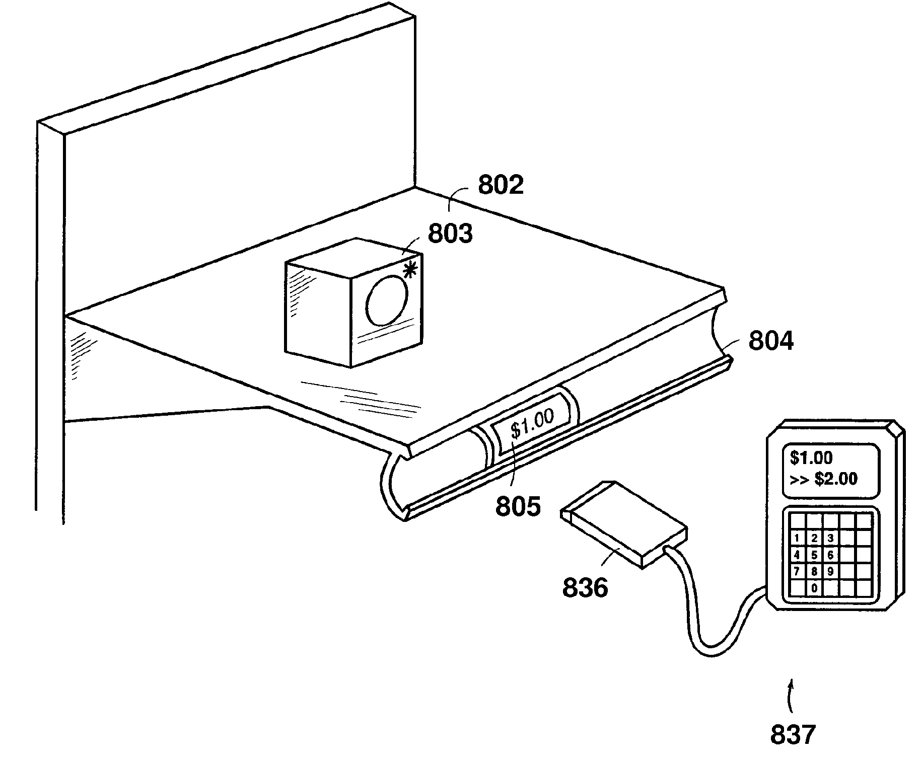
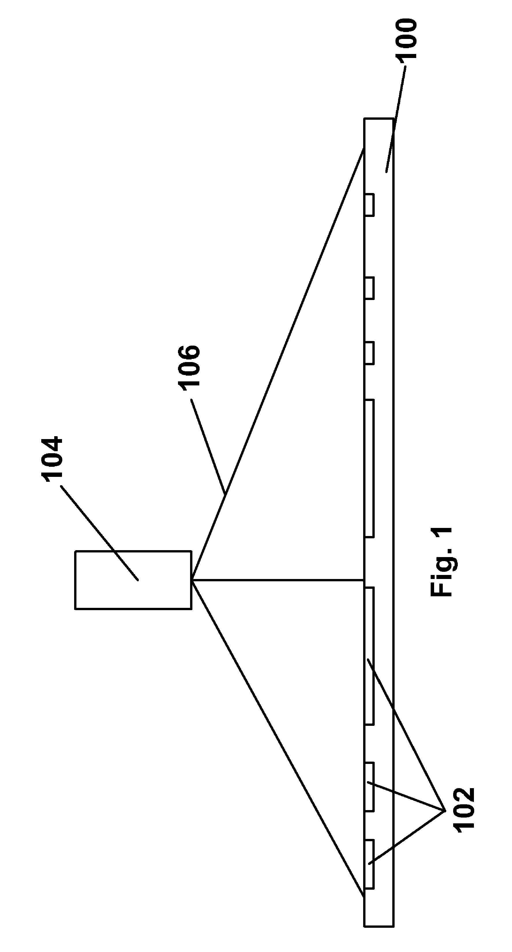
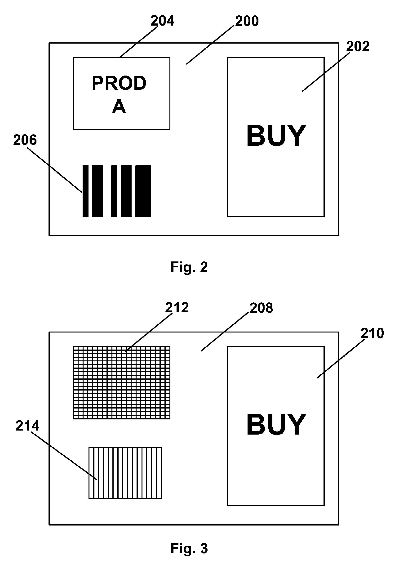
[0061]As already mentioned, in one aspect this invention provides a reflective electro-optic display having a bar code display area arranged to display a bar code readable by a bar code scanner. As discussed above with reference to FIG. 1, a bar code reader emits a scanning beam which is reflected from the bar code markings and detected by a photodetector. Since the bar code reader relies upon reflection of the scanning beam, the electro-optic display should use an electro-optic medium which is reflective rather than transmissive. The electro-optic medium need not be reflective in both its extreme optical states (typically black and white); for example, the electro-optic medium could be of the shutter mode type, with one white, reflective optical state and a substantially transparent optical state which could appear or be made to appear black to the reader (for example, by providing a black backing on the bar code display area. Also, since as already explained the bar code reader re...


PUM


Abstract

A reflective electro-optic display (200) has a bar code display area (206) arranged to display a bar code readable by a bar code scanner.

Description

REFERENCE TO RELATED APPLICATIONS[0001]This application is a continuation-in-part of copending application Ser. No. 10 / 904,233, filed Oct. 29, 2004 (Publication No. 2005 / 0122564), which itself is a continuation-in-part of application Ser. No. 09 / 564,043, filed May 3, 2000 and now abandoned, which in turn claims benefit of Application Ser. No. 60 / 132,178, filed May 3, 1999.[0002]The aforementioned application Ser. No. 10 / 904,233 also claims benefit of application Ser. No. 60 / 481,57, filed Oct. 29, 2003.[0003]This application is also related to application Ser. No. 10 / 232,481, filed Aug. 20, 2002, now U.S. Pat. No. 6,704,133.[0004]The entire contents of the aforementioned applications are herein incorporated by reference. The entire contents of all United States Patents and published and copending Applications mentioned below are also herein incorporated by reference.BACKGROUND OF THE INVENTION[0005]The present invention relates to machine-readable displays, that is to say display pri...

Claims


Application Information

Patent Timeline
Patent Type & Authority Patents(United States)
IPC IPC(8): G02B26/00
CPCG06Q30/00G09G3/344G09G3/38G09G2330/02G09G2380/04G06F3/147
Inventor ZEHNER, ROBERT W.COMISKEY, BARRETTWILCOX, RUSSELL J.
Owner E INK CORPORATION
Why Eureka
Try Eureka