
Occupant restraint apparatus

a technology for occupants and restraints, which is applied in the direction of pedestrian/occupant safety arrangements, safety belts, vehicular safety arrangements, etc., can solve the problems of defiled interior of the vehicle, damage to the inflator and/or the gas supply tube, and direct spraying of water on the inflator or dust cover, etc., to achieve good protection characteristics

Inactive Publication Date: 2011-09-13
JOYSON SAFETY SYST JAPAN KK
View PDF31 Cites 37 Cited by
  • Summary
  • Abstract
  • Description
  • Claims
  • Application Information

AI Technical Summary

Benefits of technology

[0005]An object of the present invention is to provide an occupant restraint apparatus that provides good protection characteristics for the tip side of a lap belt and an inflator, the occupant restraint apparatus having a lap belt inflatable portion into which gas of the inflator is introduced from the tip side of the lap belt.

Problems solved by technology

There is therefore a risk that the inflator is directly sprayed with water or covered with dust, or that the inflator and / or the gas supply tube are damaged due to rubbing or the like.
Furthermore, the appearance of the interior of the vehicle cabin is defiled.

Method used


Image

  • Occupant restraint apparatus
  • Occupant restraint apparatus
  • Occupant restraint apparatus

Examples


Embodiment Construction

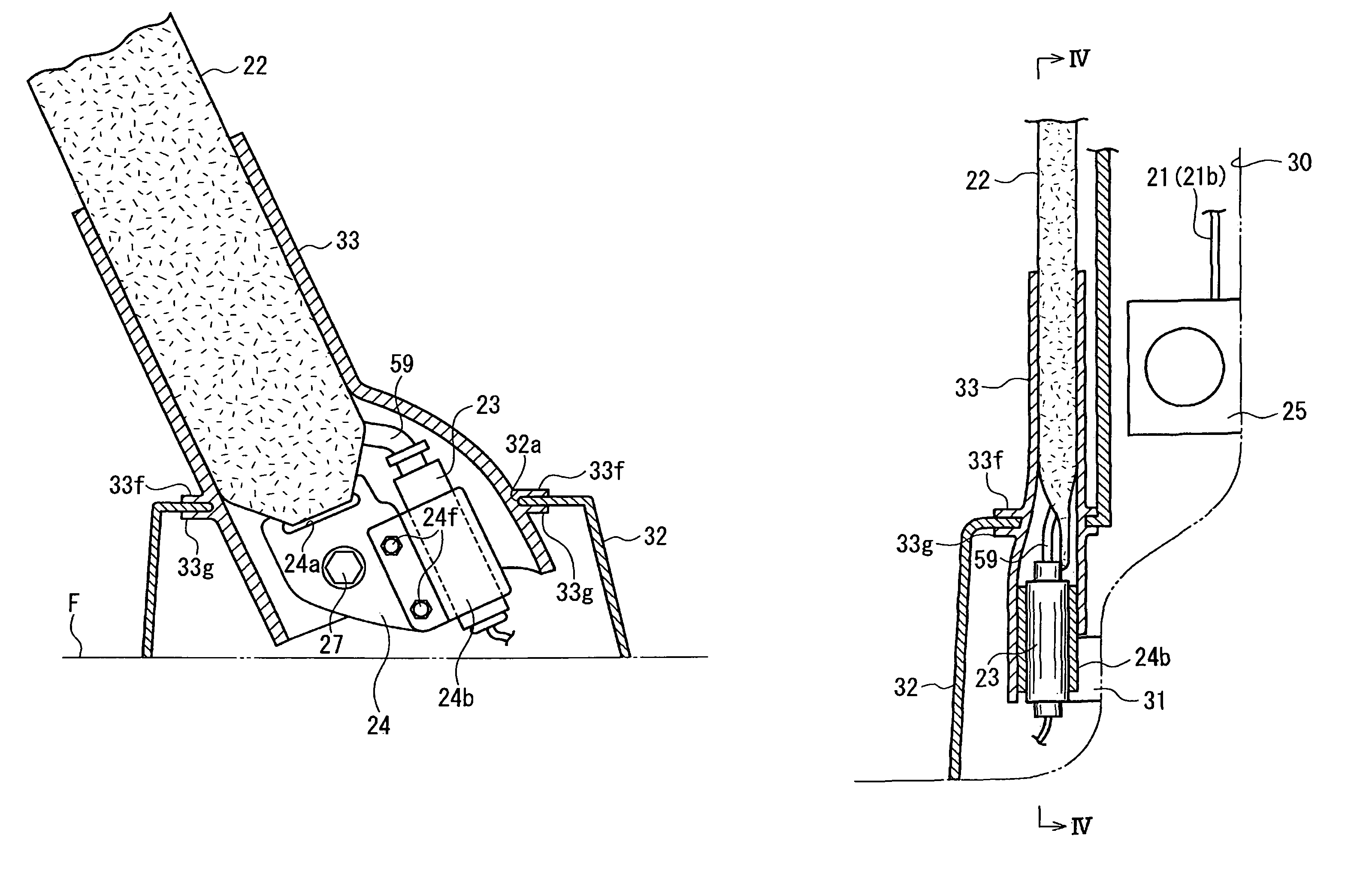
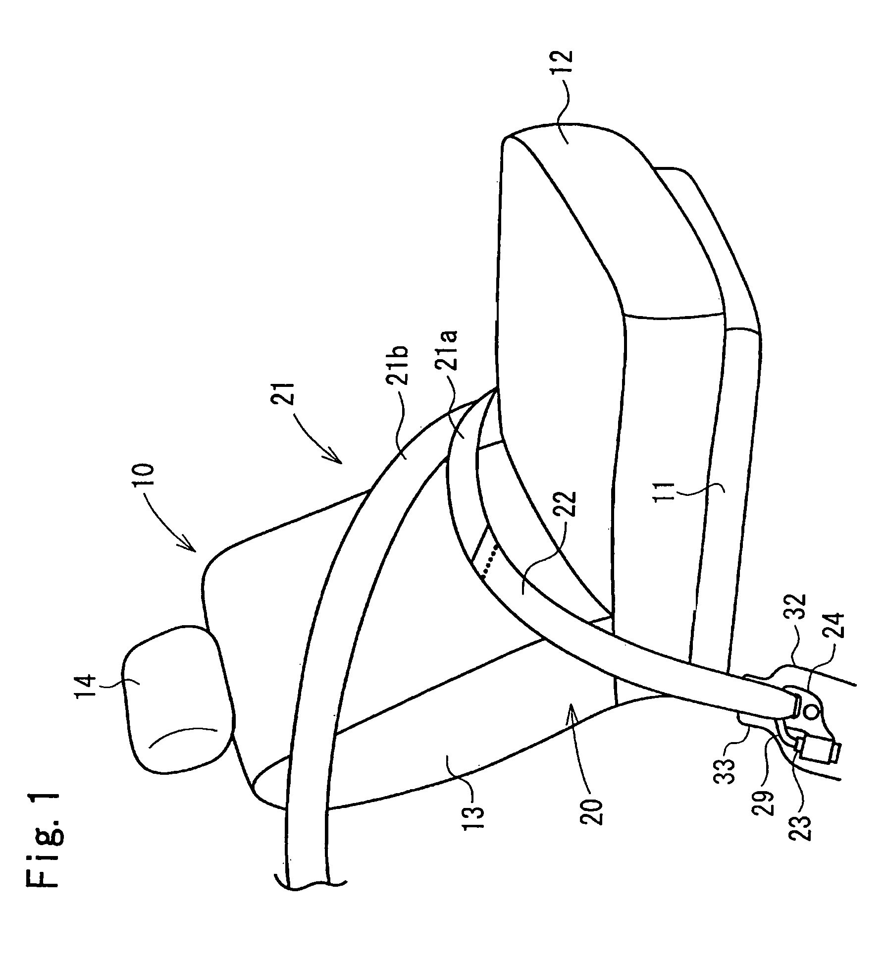
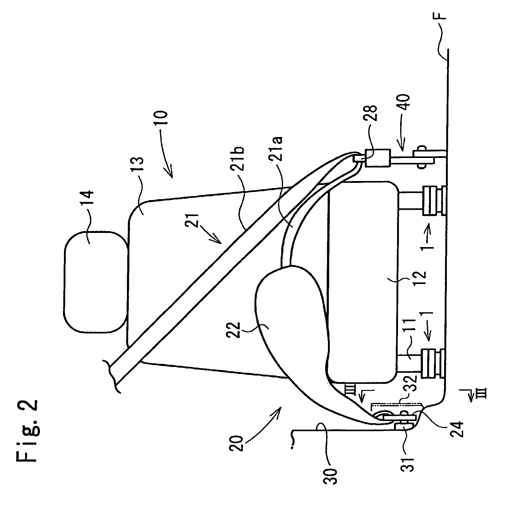
[0027]In an occupant restraint apparatus of the present invention, gas from an inflator is introduced from the tip side of a lap belt into an inflatable portion of the lap belt. In the present invention, since the tip side of the lap belt and the inflator are covered by a cover, it is prevented or suppressed that the inflator is directly sprayed with water or covered with dust, or that the inflator and / or the tip side of the lap belt are damaged due to rubbing or the like, so good protection characteristics for the tip side of the lap belt and the inflator (that is, the whole of gas supply members from the inflator to the inflatable portion of the lap belt) are therefore ensured.

[0028]In addition, since the tip side of the lap belt and the inflator are not exposed in a vehicle cabin, the appearance of the interior of the vehicle cabin is good.

[0029]Incidentally, in the occupant restraint apparatus of the present invention, when, for example, a sensor installed in a vehicle for detec...


PUM


Abstract

An occupant restraint apparatus includes an anchor adapted to be fixed to a vehicle body, a lap belt having a tip side fixed to the anchor, and an inflatable portion formed at the tip side, an inflator for introducing gas from the tip side to inflate the inflatable portion, and a cover. The cover includes a first masking portion for covering the anchor, and a second masking portion formed separately from the first masking portion and attached to the first masking portion for covering at least the tip side of the lap belt.

Description

TECHNICAL FIELD[0001]The present invention relates to an occupant restraint apparatus provided with a lap belt having an inflatable portion, which is inflated in the event of a vehicle collision or the like.BACKGROUND ART[0002]In FIG. 2 of WO 01 / 036235 (PCT Japanese Translation Patent Publication No. 2003-525797), a structure is described that has a retractor mounted on the floor of a vehicle and allows the tip side of an inflatable lap belt to be retracted by the retractor. In this prior example, an inflator is mounted on the vehicle floor and gas is introduced into the lap belt through a special structure, so called a plenum.[0003][Patent Document 1] PCT Japanese Translation Patent Publication No. 2003-525797[0004]In the PCT Japanese Translation Patent Publication No. 2003-525797, as shown in FIG. 2 thereof, an inflator and a gas supply tube connecting the inflator to a plenum (the tip side of a lap belt) are exposed in a vehicle cabin. There is therefore a risk that the inflator ...

Claims


Application Information

Patent Timeline
Patent Type & Authority Patents(United States)
IPC IPC(8): A62B35/00A62B35/04B60R22/00B60R21/23B60R21/18B60N2/42
CPCB60R21/18B60R22/22
Inventor ITOGA, YASUO
Owner JOYSON SAFETY SYST JAPAN KK
Learn More