Method and apparatus for measuring ball launch conditions

a technology of ball launch conditions and measurement methods, applied in the field of golf ball monitoring devices, can solve the problems of significant error room and limitations of human eyes, and achieve the effect of reducing the number of unknown variables

Active Publication Date: 2011-09-13
ACUSHNET CO
View PDF18 Cites 28 Cited by
  • Summary
  • Abstract
  • Description
  • Claims
  • Application Information

AI Technical Summary

Benefits of technology

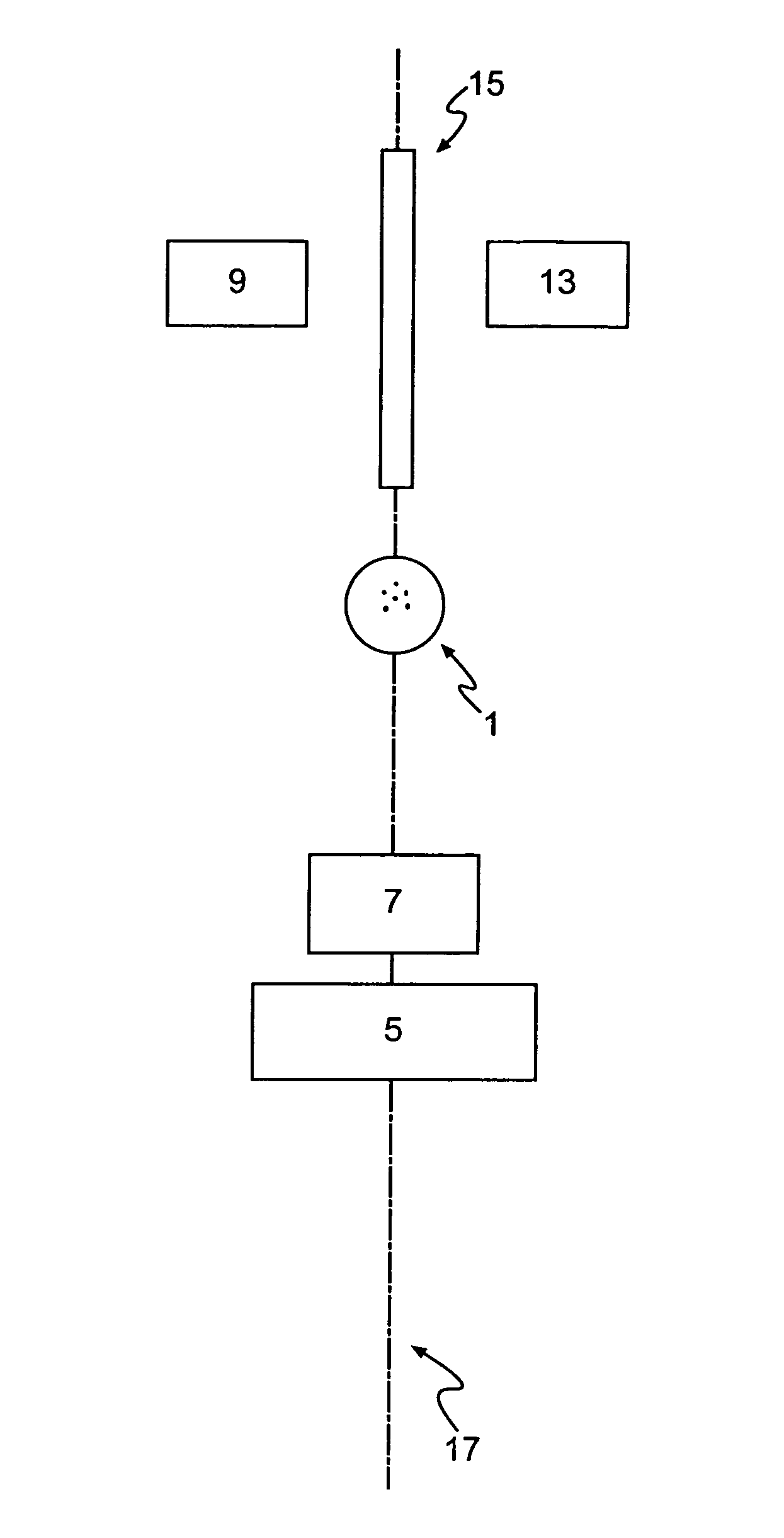
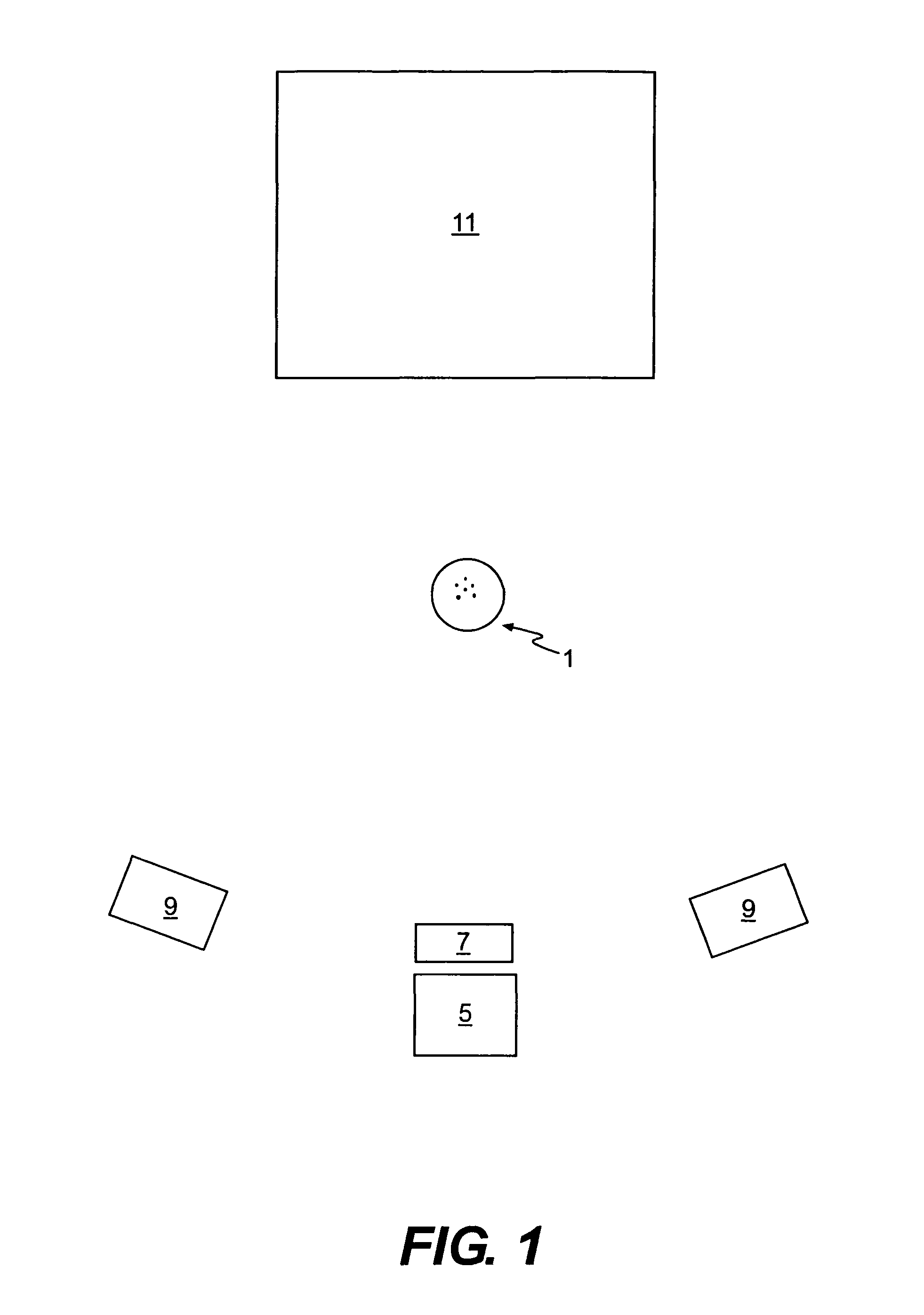
[0005]The present invention relates to a method and apparatus that is capable of reducing the number of unknown variables involved in the calculation of the kinematic characteristics of a golf ball during flight. In one embodiment, the present invention comprises an apparatus that includes an illumination device selectively positioned to illuminate a field of view with light within a predetermined wavelength range, a golf ball having a surface that reflects light within the predetermined wavelength range, and a background surface that absorbs the light within the predetermined wavelength range.
[0007]It is desirable for the background surface to comprise a high grey level surface that emits a limited spectrum of light. The illumination device may include a filter or strobe lamp. Any type of camera may be used, although a camera comprising a CCD having at least about a four megapixel resolution is preferable. The camera may include a filter to prevent light within predetermined wavelengths from being imaged.

Problems solved by technology

However, because the mechanics of swinging a golf club are complicated, there is significant room for error.
The human eye, however, has its limits.

Method used


Image

  • Method and apparatus for measuring ball launch conditions
  • Method and apparatus for measuring ball launch conditions
  • Method and apparatus for measuring ball launch conditions

Examples


Embodiment Construction

[0017]Other than in the operating examples, or unless otherwise expressly specified, all of the numerical ranges, amounts, values and percentages such as those for amounts of materials, spin, diameter, velocity, and others in the following portion of the specification may be read as if prefaced by the word “about” even though the term “about” may not expressly appear with the value, amount, or range. Accordingly, unless indicated to the contrary, the numerical parameters set forth in the following specification and attached claims are approximations that may vary depending upon the desired properties sought to be obtained by the present invention. At the very least, and not as an attempt to limit the application of the doctrine of equivalents to the scope of the claims, each numerical parameter should at least be construed in light of the number of reported significant digits and by applying ordinary rounding techniques.

[0018]Notwithstanding that the numerical ranges and parameters ...


PUM


Abstract

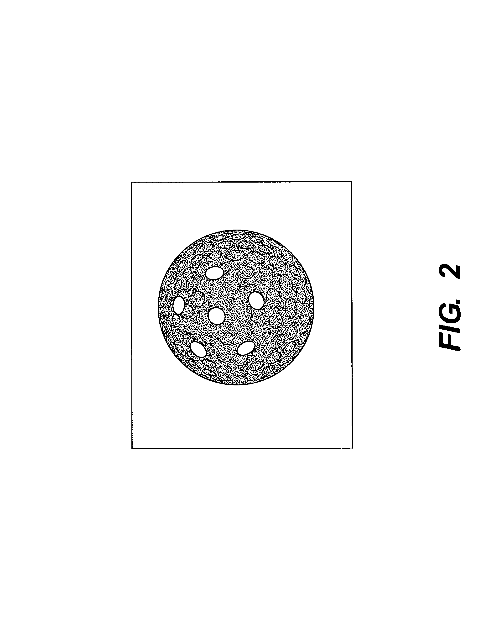
A method and apparatus for measuring ball launch conditions is disclosed. Specifically, the accuracy of the calculations used to determine the kinematic characteristics may be increased. A background image of a field of view, without a golf ball present, may be acquired. Two or more images of a golf ball in motion are then be acquired based on positive or negative imaging. The background image is subtracted from each of the two or more images of the golf ball. After subtracting the background image, the two or more images of the golf ball are analyzed to determine the location of the circular perimeter of the golf ball. Based on the location of the circular perimeter of the golf ball, the location of the center of the golf ball may be calculated. Knowing the location of the center of the golf ball increases the accuracy of measurements of kinematic characteristics such as sidespin, backspin, velocity, and launch angle.

Description

FIELD OF THE INVENTION[0001]The present invention relates to golf ball monitoring devices. More particularly, the present invention relates to an improved method and apparatus for measuring ball launch conditions.BACKGROUND OF THE INVENTION[0002]Golf players are continuously searching for better equipment with the ultimate goal of using that equipment to improve their game by lowering their score. However, because the mechanics of swinging a golf club are complicated, there is significant room for error. In order for a golfer to improve their swing, they must be able to swing a club consistently in an appropriate manner. Often, golfers need the assistance of a coach in order to attain a consistent swing that strikes the golf ball in a desirable manner. The human eye, however, has its limits. In order to provide more information to golfers, golf equipment manufacturers have invented ball monitoring devices, commonly referred to as “launch monitors.” Launch monitors are capable of pro...

Claims


Application Information

Patent Timeline
Patent Type & Authority Patents(United States)
IPC IPC(8): A63B69/36A63F13/00
CPCA63B24/0021A63B69/3614A63B69/3658A63B2024/0031A63B2220/35
Inventor GOBUSH, WILLIAM
Owner ACUSHNET CO
Why Eureka
Try Eureka