Propellant management system and method for multiple booster rockets

a technology of propellant management system and booster rocket, which is applied in the field of booster vehicles, can solve the problems of increasing the difficulty of simultaneous depleting liquid propellant, affecting the performance of the booster rocket, and the risk that the rocket will not run out of propellant, so as to reduce the amount of propellant and increase the throttle

Inactive Publication Date: 2011-09-13
LOCKHEED MARTIN CORP
View PDF35 Cites 6 Cited by
  • Summary
  • Abstract
  • Description
  • Claims
  • Application Information

AI Technical Summary

Benefits of technology

[0009]Various refinements exist of the features noted in relation to the first aspect of the present invention. Further features may also be incorporated in the first aspect of the present invention as well. These refinements and additional features may exist individually or in any combination. Typically the rocket that is running faster (having the lesser amount of the propellant constituent(s) being compared) will be “throttled down.” However, the differential propellant logic could send the first signal to the throttle valve of a rocket that is running slower (having a larger amount of the propellant constituent(s) being compared), so as to “increase the throttle” of this rocket.
[0011]The propellant logic may calculate the amount of the propellant constituent of a particular rocket in any appropriate manner. In one embodiment, the mass of propellant constituent in a given tank is calculated by measuring the pressure at the bottom of its corresponding tank, and taking into account the density of the propellant constituent and the acceleration level of the volume of the propellant constituent within the tank. In some cases, an axial acceleration imbalance may exist between two or more rockets due to the existence of an angular acceleration. In this regard, the launch vehicle may include axial acceleration logic that adjusts the acceleration level that is used to convert a pressure head to a propellant mass to enhance the accuracy of the mass determination. Generally, the axial acceleration logic may estimate / calculate an axial acceleration that is the product of the angular acceleration (e.g., computable by numerically differentiating multiple rate gyro signals) and a moment arm coinciding with the distance between the longitudinal centerlines of a pair of rockets.
[0019]The launch vehicle and boosters each may be of any appropriate configuration. In one embodiment, the boosters are simultaneously shut down at the appropriate time and thereafter simultaneously jettisoned from the launch vehicle. The second aspect may be characterized as minimizing the amount of propellant remaining in the boosters when they are shut down and jettisoned from the launch vehicle. Although it would of course be preferable for the propellant to be completely depleted in each of the boosters at the time of shut down, more typically a certain amount of propellant will remain in one or more of the boosters at the time of the shut down.
[0021]In one embodiment, the mass of the first propellant constituent in the first tank of a particular booster is calculated by measuring the pressure at the bottom of this first tank, and taking into account the density of the first propellant constituent and the acceleration level of the volume of the first propellant constituent within this first tank. In some cases, an axial acceleration imbalance may exist between the first and second boosters due to the existence of an angular acceleration. In this regard, the launch vehicle may include axial acceleration logic that adjusts the acceleration level that is used to convert a pressure head to a propellant mass to enhance the accuracy of the mass determination. Generally, the axial acceleration logic may estimate / calculate an axial acceleration that is the product of the angular acceleration (e.g., computable by numerically differentiating multiple rate gyro signals) and a moment arm coinciding with the distance between the longitudinal centerlines of the first and second boosters.
[0030]A second throttle regulator valve associated with the second booster may be controlled in the same manner as the first throttle regulator valve of the first booster. Typically a control signal will be sent the booster that is running faster (having the lesser amount of the propellant constituent(s) being compared), so as to “throttle down” this booster. However, a control signal could be sent to the throttle valve of a booster that is running slower (having a larger amount of the propellant constituent(s) being compared), so as to “increase the throttle” of this booster.

Problems solved by technology

Simultaneously depleting liquid propellants becomes more complicated when the booster stage comprises more than one rocket.
While each rocket is designed and calibrated to burn a specified amount of propellant each second, there can be noticeable variations due to actual operating conditions, acceptance test inaccuracies and other unforeseen occurrences.
As a consequence, there exists a risk that the rockets will not run out of propellant at the same time.
This is disadvantageous because once one of the rockets has gone below a threshold propellant level, the flight computer will shut down all similar stage rockets and jettison them even though propellant remains in the other rockets.
The unused propellant ends up being “dead weight” that was carried aloft unnecessarily by the launch vehicle, affecting the lift capability of the system.

Method used


Image

  • Propellant management system and method for multiple booster rockets
  • Propellant management system and method for multiple booster rockets
  • Propellant management system and method for multiple booster rockets

Examples


Embodiment Construction

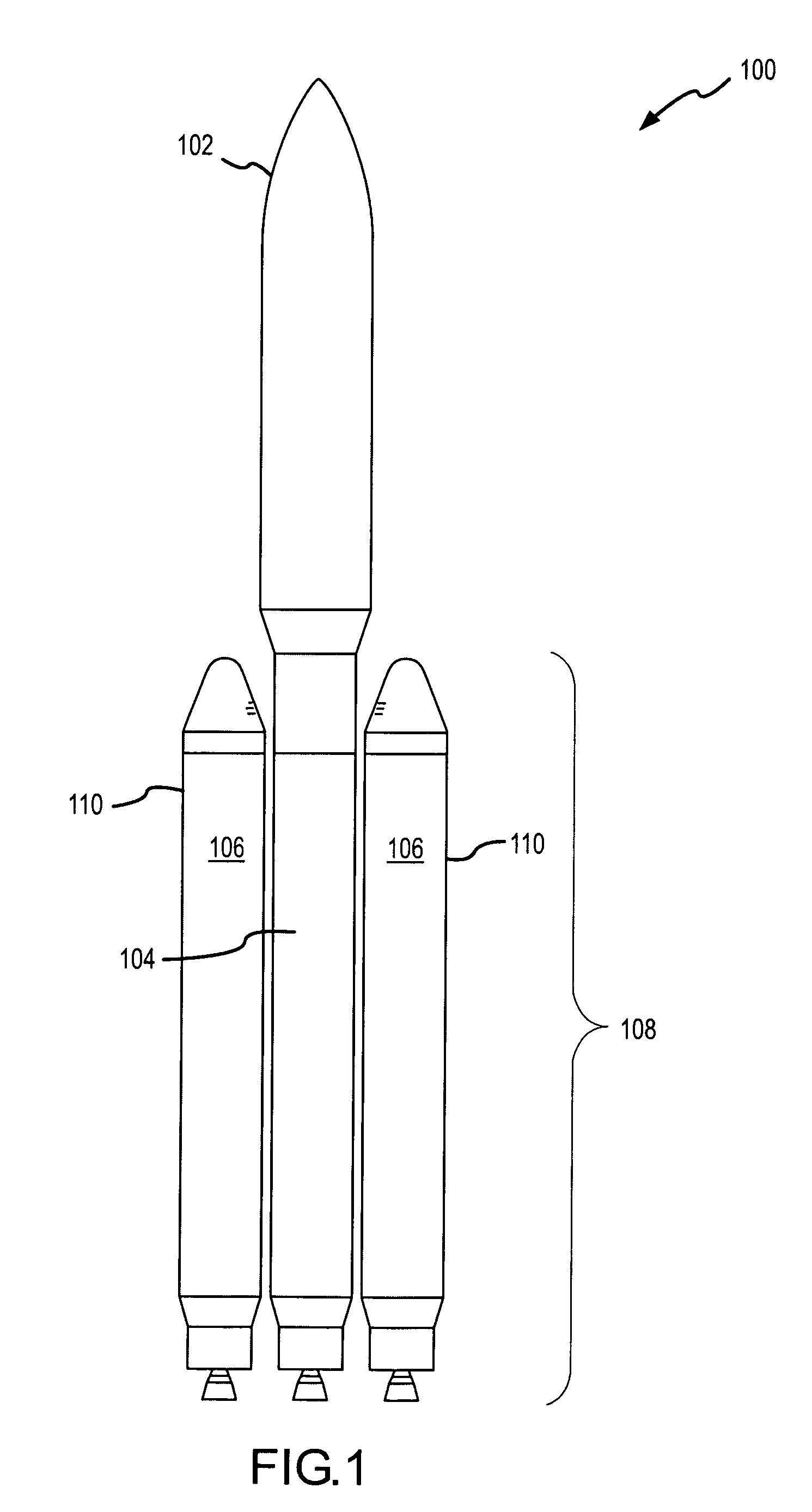
[0062]Reference will now be made to the accompanying drawings, which at least assist in illustrating the various pertinent features of the present invention. FIG. 1 illustrates one embodiment of a space vehicle 100. The space vehicle 100 generally includes a payload 102 and a launch vehicle 108, which comprises a first thrust source 110 and a second thrust source 104. As depicted, the space vehicle 100 comprises one rocket for the second thrust source 104. It will also be appreciated that any appropriate number of rockets could be used by the second thrust source 104. Also as depicted, the first thrust source 110 comprises two liquid propellant strap-on rockets or boosters 106. It should be appreciated that any appropriate number of liquid propellant rockets 106 may be utilized by the space vehicle 100. For instance, the first thrust source 110 could comprise more than two liquid propellant rockets 106, such as 3, 4, 5, 6, 7, 8 or more rockets 106. Various ways of controlling the op...


PUM


Abstract

Propellant management systems and methods are provided for controlling the delivery of liquid propellants in a space launch vehicle utilizing multiple rockets. The propellant management systems and methods may be configured to enable substantial simultaneous depletion of liquid propellants in each of a plurality of active rockets during operation of various booster stages of the launch vehicle.

Description

CROSS REFERENCE TO RELATED APPLICATIONS[0001]This application is a divisional of and claims priority from U.S. application Ser. No. 11 / 060,672 filed Feb. 17, 2005 and titled “PROPELLANT MANAGEMENT SYSTEM AND METHOD FOR MULTIPLE BOOSTER ROCKETS”, which application claims priority from U.S. Provisional Application Ser. No. 60 / 546,524, filed Feb. 20, 2004, and titled “DIFFERENTIAL ENGINE THROTTLING TO MINIMIZE PROPELLANT OUTAGES IN LIQUID STRAP-ON BOOSTERS”, and from U.S. Provisional Application Ser. No. 60 / 557,603, filed Mar. 30, 2004, and titled “DIFFERENTIAL LIQUID ROCKET BOOSTER PROPELLANT MANAGEMENT”, each of which are incorporated herein by reference in their entirety.FIELD OF THE INVENTION[0002]This invention is related to the field of launch vehicles for use in launching a payload from a stationary ground-based position into orbit, and specifically to apparatus, systems and methods for managing propellant usage and delivery in multiple, active rockets.BACKGROUND OF THE INVENTIO...

Claims


Application Information

Patent Timeline
Patent Type & Authority Patents(United States)
IPC IPC(8): B64G1/40
CPCB64G1/401B64G1/402F02K9/42F02K9/48F02K9/56F05D2270/31F05D2270/13
Inventor MANGO, FRANK S.
Owner LOCKHEED MARTIN CORP
Why Eureka
Try Eureka