Device for locking containers

a container and device technology, applied in the direction of limiting/preventing/returning parts movement, carpet fasteners, dwelling equipment, etc., can solve the problem that both types of locks cannot secure the padlock shackle from being cu

Inactive Publication Date: 2011-09-20
SOLEX INT (THAILAND) CO LTD
View PDF26 Cites 16 Cited by
  • Summary
  • Abstract
  • Description
  • Claims
  • Application Information

AI Technical Summary

Problems solved by technology

However, both types of locks are unable to secure the padlock shackle from being cut.

Method used


Image

  • Device for locking containers
  • Device for locking containers
  • Device for locking containers

Examples


Embodiment Construction

.”

BRIEF DESCRIPTION OF THE DRAWINGS

[0008]Features, aspects, and embodiments are described in conjunction with the attached drawings, in which:

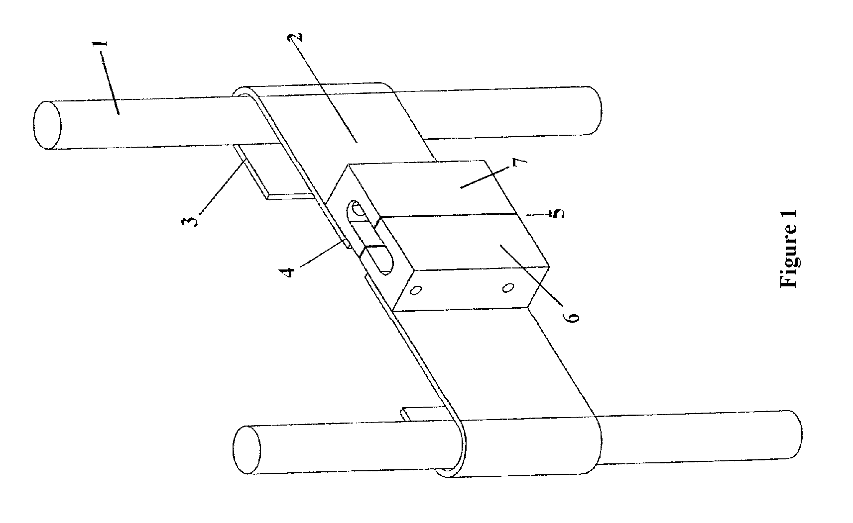
[0009]FIG. 1 illustrates the front view of the Container-Locking Device with respect to this particular invention.

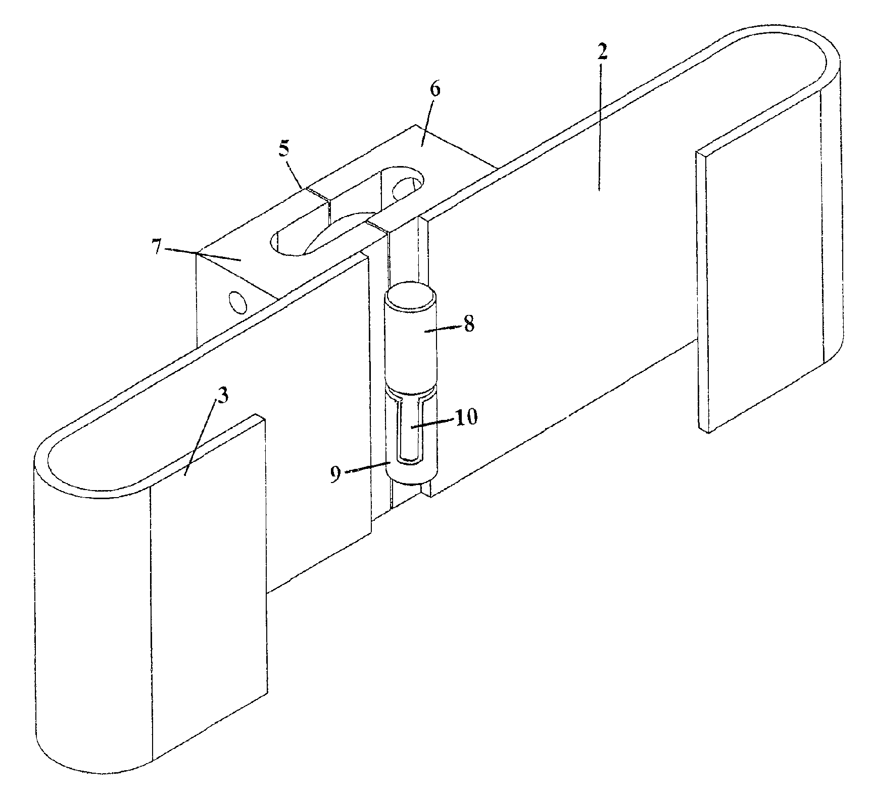
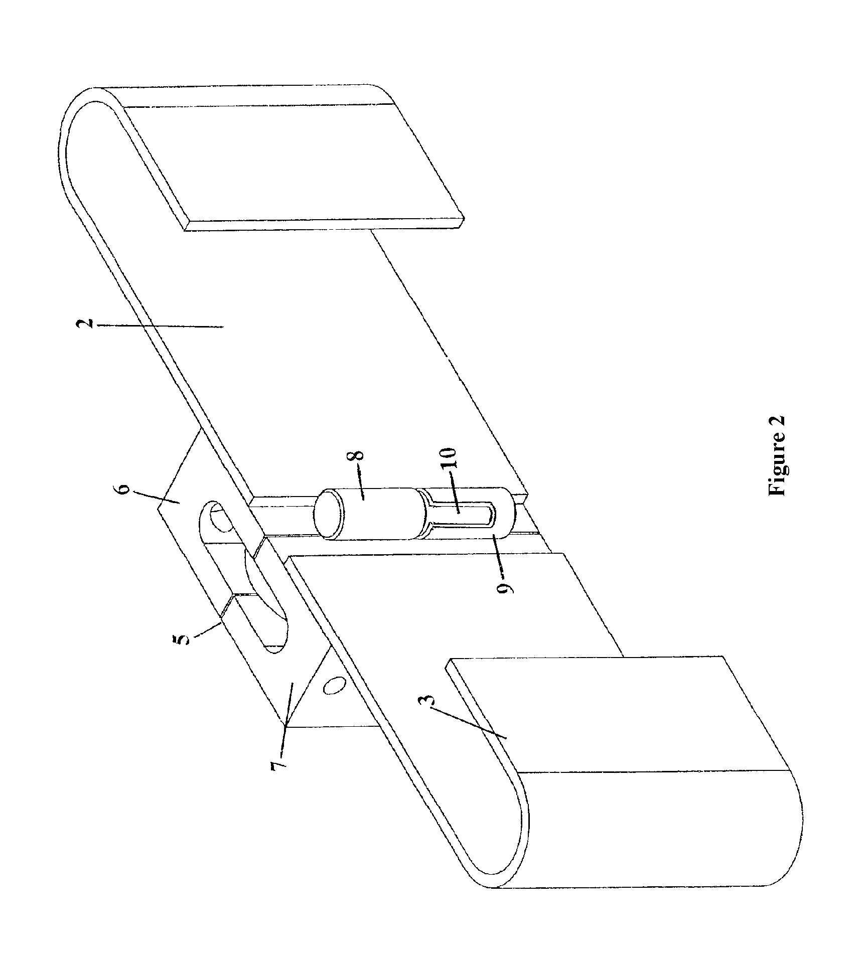
[0010]FIG. 2 illustrates the back view of the Container-Locking Device, showing the padlock shroud separation-prevention unit, connected to the back side of the mechanism with respect to this particular invention.

[0011]FIG. 3 illustrates the cutaway view of the Container-Locking Device with respect to this particular invention, illustrating the structure of the padlock compartment.

DETAILED DESCRIPTION OF THE DRAWINGS

[0012]FIG. 1 illustrates the front view of the Container-Locking Device configured in accordance with the embodiments described herein. Specifically for use with freight containers with a pair of container door locking bars (1). The mechanism is comprised of a pair of hardened steel, bolt cutter-resistant locking bar fa...


PUM


Abstract

The Container-Locking Device with respect to this particular invention has been designed to fasten the locking upright bar of one door of a container to another. It has been invented to include two virtually symmetrical segments of a pair of locking bar fasteners, where the flat end of each segment, opposite to the end fastened to the container door locking bar, will be fixed to one of the two virtually symmetrical segments of a padlock shroud. There is also a separation-prevention unit which prevents the shroud from being separated and eliminates the gap between the two segments when they are joined, in order to prevent a bolt cutter from being able to be inserted into the padlock shackle.

Description

RELATED APPLICATION[0001]The present application claims priority under 35 U.S.C. §119(a) to Thailand Patent Application No. 0801004232, filed in the Thailand Department of Intellectual Property Office on Aug. 14, 2008, which is incorporated by reference in its entirety as if set forth in full.BACKGROUND[0002]1. Technical Field[0003]In general, this particular invention relates to anti-theft devices to protect goods stored in containers, and in particular devices for locking containers.[0004]2. Related Art[0005]Many different types of anti-theft devices are used extensively to help prevent goods stored inside a freight container being stolen. One of these is a regular type of lock similar to a hinge and staple set for securing house doors, comprised of a long metal plate fixed to one side of a container's doors, which can be swiveled sideways around the axis it is connected to, like a hinge. The middle section at the end of the independent plate is cut into a rectangular space, throu...

Claims


Application Information

Patent Timeline
Patent Type & Authority Patents(United States)
IPC IPC(8): E05B67/38
CPCE05B67/383E05C19/186B65D2211/00Y10S70/43Y10S70/56Y10S292/32Y10T70/40Y10T70/498Y10T70/5031Y10T70/5726Y10T70/5779Y10T292/1049Y10T292/228
Inventor PITISETHAKARN, EKAPHAN
Owner SOLEX INT (THAILAND) CO LTD
Why Eureka
Try Eureka