Method of deployment for real time casing imaging

a casing and imaging technology, applied in the field of fiber optic sensor imaging, can solve the problems of high stress, high temperature, high pressure, and harsh environment of casings disposed in boreholes

Active Publication Date: 2011-09-27
BAKER HUGHES HLDG LLC
View PDF22 Cites 57 Cited by
  • Summary
  • Abstract
  • Description
  • Claims
  • Application Information

AI Technical Summary

Problems solved by technology

Structures such as casings disposed in boreholes can be exposed to harsh environments.
The harsh environments include high temperature, high pressure, and high stress.
The high stress can result from the high temperature, the high pressure, high loads or high vibration.
While fiber optics may be able to withstand the pressures and temperatures of the harsh downhole environment, fiber optics are delicate and require careful and precise installation especially when installing the splices.
Unfortunately, installing the splices on the floor of a completion rig is not conducive to the care and precision required for a reliable and working installation.
Another problem can arise when a faulty sensor is first inserted into the borehole before a splice is made coupling the sensor to the fiber optic communication cable.
In this case, the faulty sensor can be far down the borehole before the fault is detected resulting in wasted time to remove the sensor from the borehole for repair or replacement.
Thus, much time is required for a custom installation, and the rework time to repair or replace a faulty RTCI fiber optic sensor can be considerable.

Method used


Image

  • Method of deployment for real time casing imaging
  • Method of deployment for real time casing imaging
  • Method of deployment for real time casing imaging

Examples


Embodiment Construction

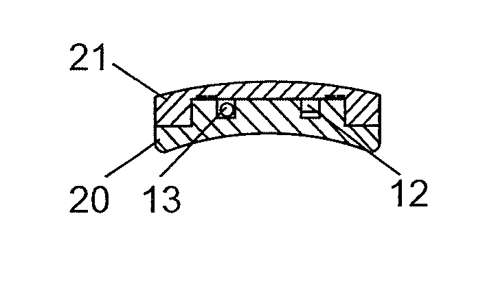
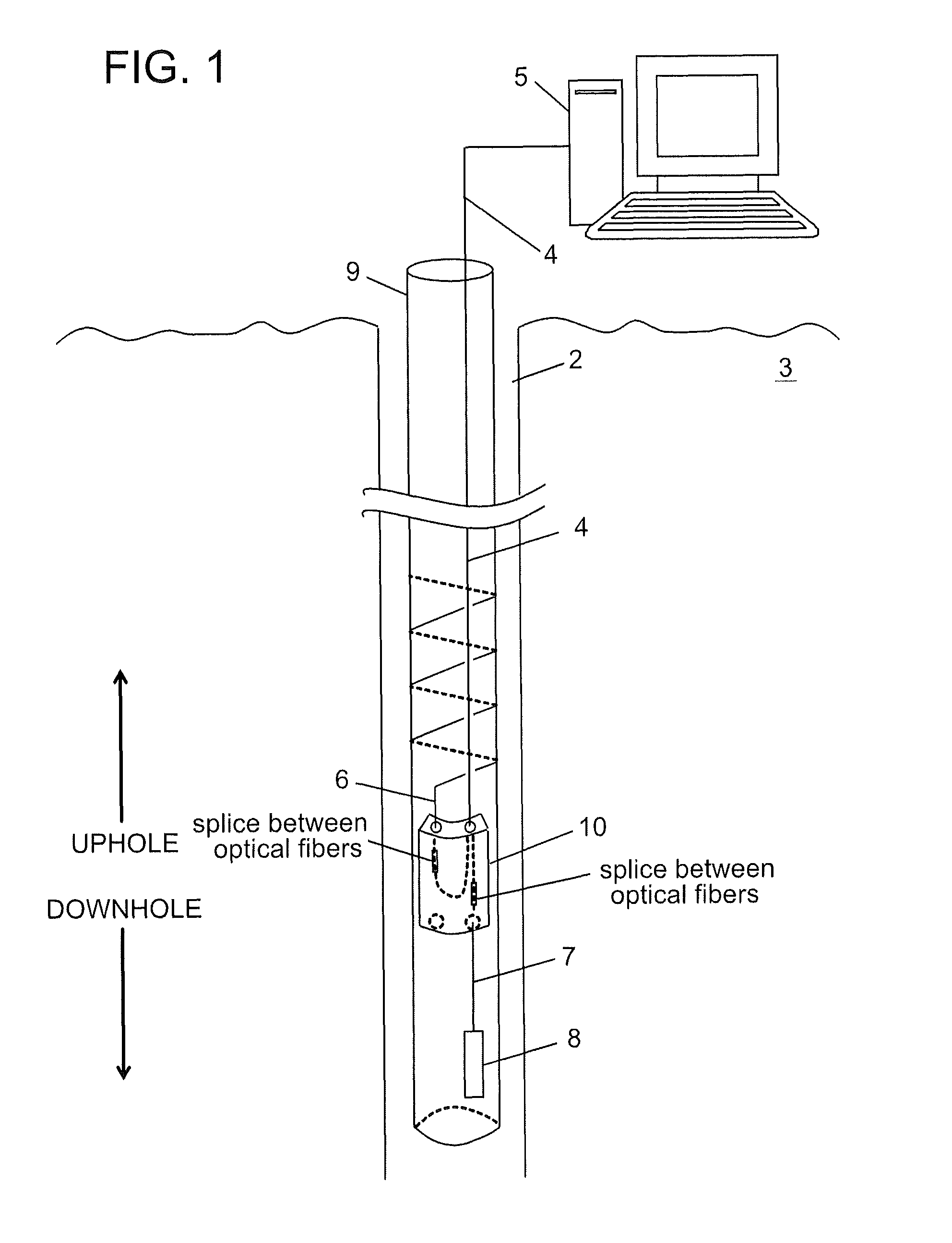
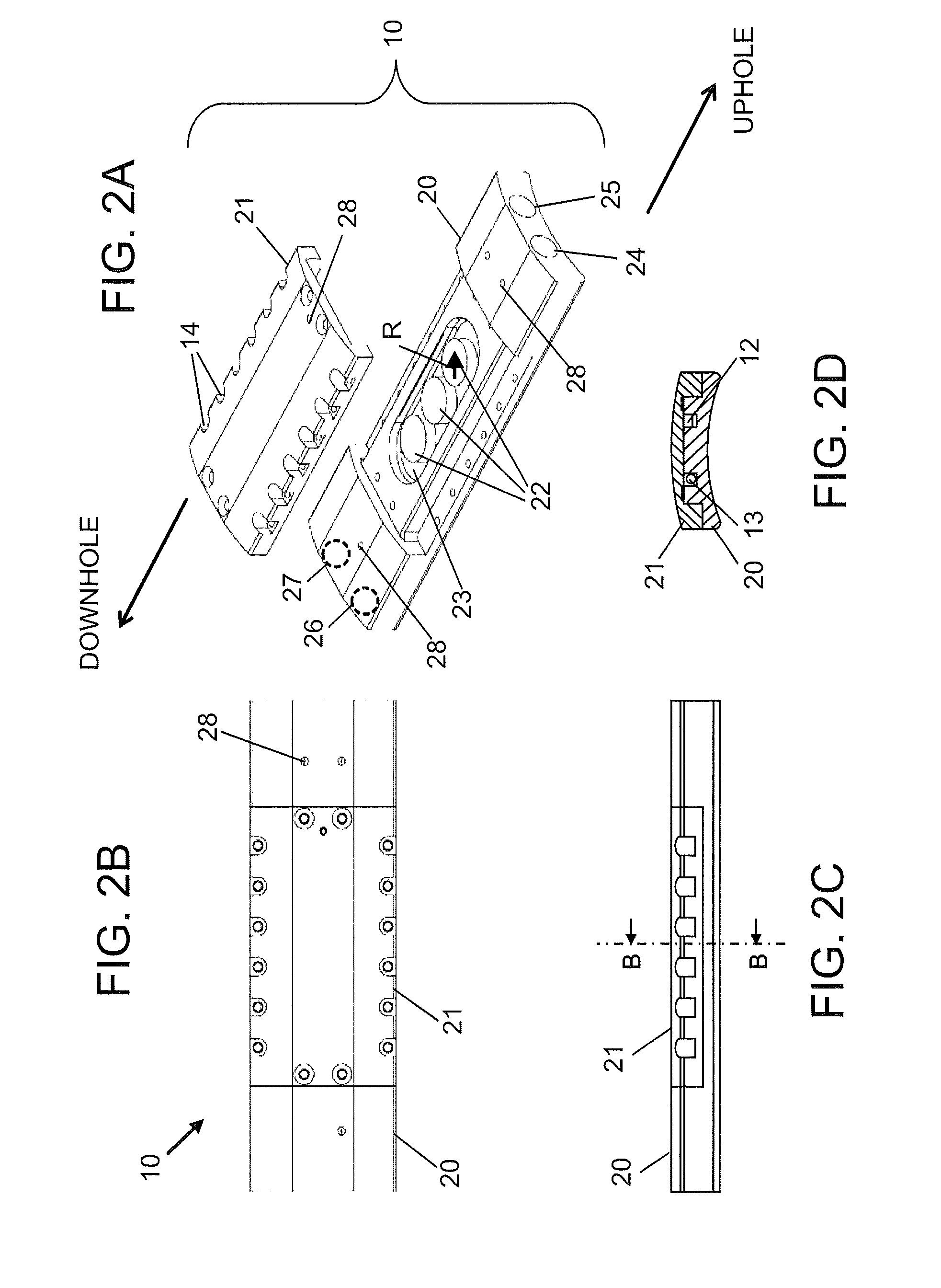
[0020]Disclosed are exemplary embodiments of techniques for deploying a fiber optic communications cable and a fiber optic strain sensor (or any fiber optic sensor) in a borehole penetrating the earth. The fiber optic strain sensor is configured to be in optical communication with a fiber optic processing unit via the fiber optic communications cable. Because the strain sensor is separate from the fiber optic communications cable, a splice is required to couple the fiber optic strain sensor to an assigned optical fiber in the fiber optic communications cable. The techniques, which include method and apparatus, call for installing the splice below the strain sensor such that the splice is disposed in the borehole before the strain sensor. In this manner, the fiber optic strain sensor can be tested or made operational before being disposed in the borehole.

[0021]The techniques disclosed herein use an optical fiber splice housing for protecting the splice between two optical fibers from...


PUM

PropertyMeasurementUnit
pressure resistantaaaaaaaaaa
lengthaaaaaaaaaa
curvatureaaaaaaaaaa

Abstract

A method for imaging a structure disposed in a borehole penetrating the earth, the method including: selecting a splice housing having a first port configured to seal the housing to a first fiber optic cable and a second port configured to seal the housing to a fiber optic sensor configured to image the structure, wherein the housing includes a sealed interior volume sufficient to contain a splice of optical fibers for protection and to enable a functional bend of at least ninety degrees for at least one spliced optical fiber; disposing a splice between an optical fiber of the first fiber optic cable and an optical fiber of the fiber optic sensor in the splice housing; disposing the splice housing containing the splice in the borehole; attaching the fiber optic sensor to the structure; and disposing the structure in the borehole after the splice housing is disposed in the borehole.

Description

BACKGROUND OF THE INVENTION[0001]1. Field of the Invention[0002]The invention disclosed herein relates to method and apparatus for imaging a structure downhole and, in particular, to imaging using a fiber optic sensor.[0003]2. Description of the Related Art[0004]Hydrocarbons are generally recovered through boreholes penetrating reservoirs of the hydrocarbons. Various types of structures may be disposed in the boreholes for the recovery process. During well completion, one type of structure known as a casing or tubular is disposed in a borehole. The casing, similar to a pipe, is used to contain the hydrocarbons flowing to the surface of the earth for recovery.[0005]Structures such as casings disposed in boreholes can be exposed to harsh environments. The harsh environments include high temperature, high pressure, and high stress. The high stress can result from the high temperature, the high pressure, high loads or high vibration. Because of the high cost of well completion, it is im...

Claims


Application Information

Patent Timeline
Patent Type & Authority Patents(United States)
IPC IPC(8): G02B6/255G02B6/00
CPCE21B47/011G02B6/4446E21B47/123Y10T29/49826E21B47/017E21B47/135
Inventor RAMBOW, FREDERICK HENRY KREISLERDAVIS, BRAD W.CHILDERS, BROOKSHALL, TRAVISABSHIRE, PHILLIP EDWARD
Owner BAKER HUGHES HLDG LLC
Why Eureka
Try Eureka