Separating ring

a separating ring and ring technology, applied in the field of integrated separating rings, can solve the problems of increasing the time of dental surgery, placing errors, storage and managing numerous wedges, etc., and achieve the effect of convenient fi

Active Publication Date: 2011-10-04
HO PHILLIP PHUNG I
View PDF16 Cites 7 Cited by
  • Summary
  • Abstract
  • Description
  • Claims
  • Application Information

AI Technical Summary

Benefits of technology

The separating ring in accordance with the present invention has a resilient body being a bent open ring and having two bent side bars and two wedge legs being of flat-spearheaded shape. The bent side bars have distal ends and provide a resilient force when separated. The wedge legs are formed respectively on and protrude transversely from the distal ends of the bent side bars to allow the wedge legs to fit easily between adjacent teeth. Because the wedge legs are of flat-spearheaded shape, they easily fit between two adjacent teeth and make dental procedures including composite filling restorations easier to carry out.

Problems solved by technology

However, keeping the ring (91) open requires a considerable force and inserting the legs (911) between the adjacent tooth (82) and the matrix (92) requires great skill and is complicated by keeping the ring open (91), which may lead to placement errors and increase time of the dental surgery, especially important when the dental surgery must be completed within a limited time.
However, storing and managing numerous wedges (93) of various sizes becomes a burden in maintaining a correct work area.

Method used


Image

  • Separating ring
  • Separating ring
  • Separating ring

Examples


Embodiment Construction

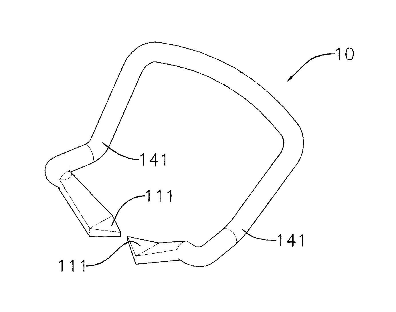
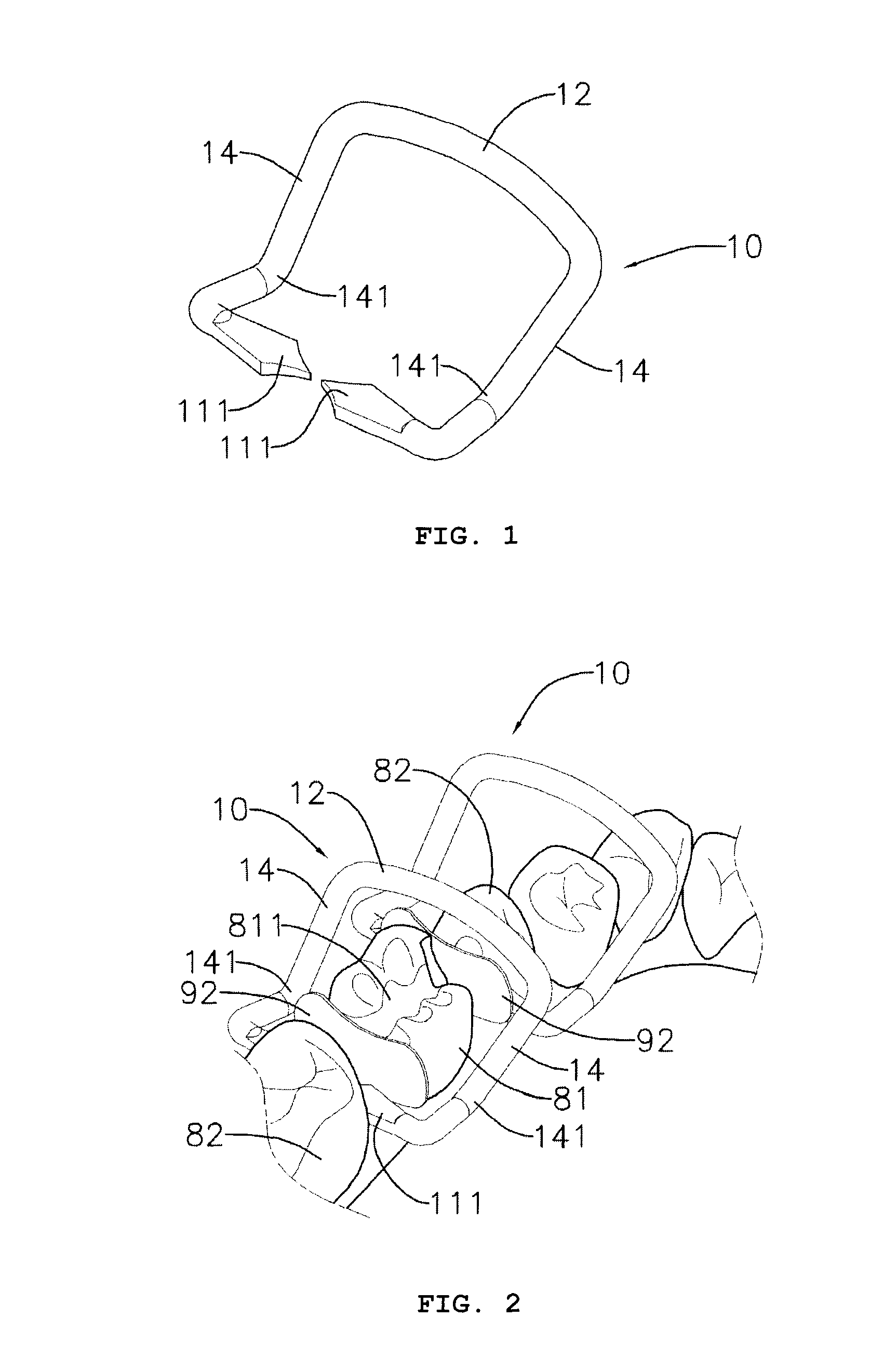
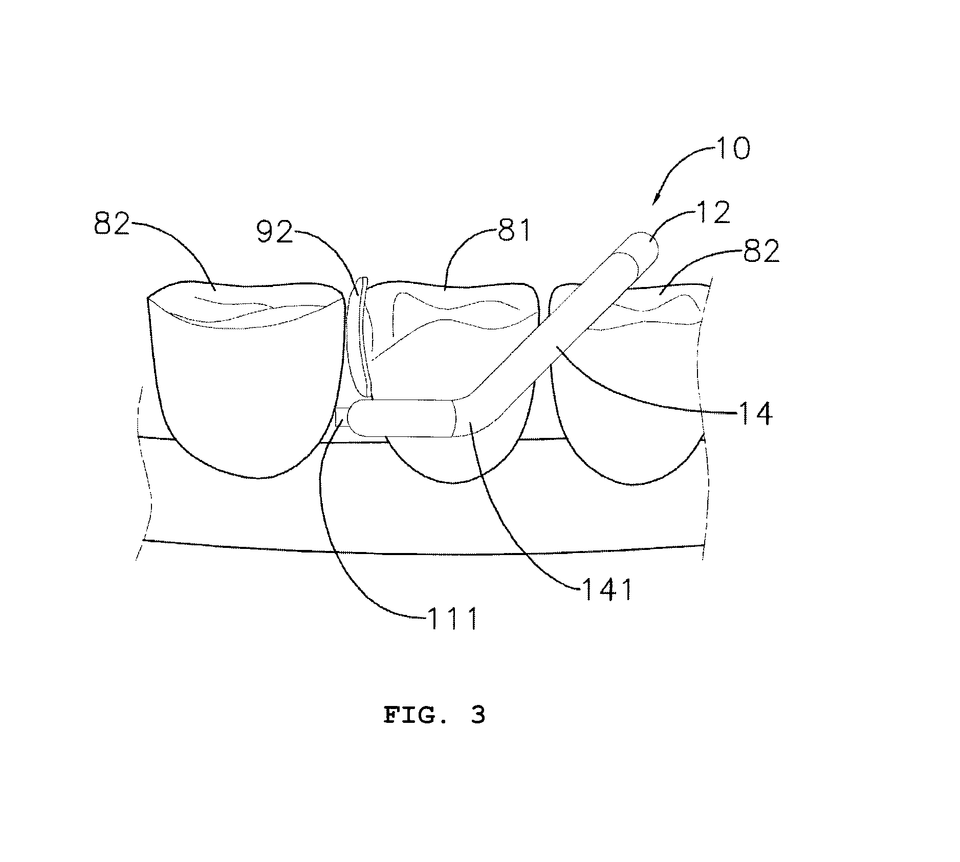
With reference to FIG. 1, a separating ring in accordance with the present invention is used to separating a decayed tooth (81) having an approximal surface from at least one adjacent tooth (82) and comprises a body (10) being a resilient open ring. The body (10) is mounted between the decayed tooth (81) and the adjacent tooth (82) and comprises a rear bar (12), two bent side bars (14) and two wedge legs (111). The body (10) may be metal or metal alloys such as but not limited to titanium and its alloys and steel and its alloys.

The rear bar (12) may be wider than the adjacent tooth (82), may be straight or curved and has two ends. The bent side bars (14) are formed on and protrude respectively from ends of the rear bar (12). Each of the bent side bars (14) has a distal end and a proximal end. The proximal end is connected to the rear bar (12). The proximal ends of the bent side bars (14) may be disposed wider than the distal ends of the bent side bars so that when the body (10) is f...


PUM


Abstract

A separating ring having a body being a resilient bent open ring and having two bent side bars having distal ends and wedge legs formed respectively on the distal ends, the wedge legs being spearheaded and fit easily between adjacent teeth to allow dental operations to be carried out easily and without the need for wedges.

Description

BACKGROUND OF THE INVENTION1. Field of the InventionThe present invention relates to an integrated separating ring for separating adjacent teeth.2. Description of the Prior ArtWith reference to FIGS. 6 and 7, a conventional separating ring (91) is a resilient open ring used to separate adjacent teeth and comprises two ends having two perpendicular extending legs (911) formed parallelly with each other. The separating ring (91) is implemented with a matrix (92) and a wedge (93). The wedge (93) is carefully selected to ensure a correct size.In dental surgery such as a dental restoration, a decayed tooth (81) having a hole (811) to be clinically treated and an outer surface having at least one adjacent surface is isolated from at least one adjacent tooth (82). A conventional method for separating the adjacent tooth (82) from the decayed tooth (81) comprises inserting the matrix (92) between the adjacent surface of the decayed tooth (81), mounting the legs (911) of the separating ring (...

Claims


Application Information

Patent Timeline
Patent Type & Authority Patents(United States)
IPC IPC(8): A61C3/00
CPCA61C5/127A61C5/88
Inventor HO, PHILLIP PHUNG-I
Owner HO PHILLIP PHUNG I
Why Eureka
Try Eureka