Method for installing run channel for automobile

a technology for installing run channels and automobile doors, which is applied in the direction of programmed manipulators, manufacturing tools, transportation and packaging, etc., can solve the problems of contributing to man-hour reduction, achieve accurate and automatic installation, and reduce the burden of large amoun

Inactive Publication Date: 2011-10-11
HONDA MOTOR CO LTD
View PDF14 Cites 1 Cited by
  • Summary
  • Abstract
  • Description
  • Claims
  • Application Information

AI Technical Summary

Benefits of technology

[0009]According to the present invention, a run channel for an automobile door being a long soft object can be installed accurately and automatically in a sash of an automobile door. In addition, improvement and stabilization in quality of installation of a run channel for an automobile door can be attained.
[0010]Also, according to the present invention, with an operation of a roller with deflection of a supporting member, a soft member such as a run channel for an automobile door being a long soft object can be installed accurately and automatically in a concave groove present in a substantially concave member in section such as a sash of an automobile door without causing control means to bear a large burden. In addition, improvement and stabilization in quality of installation of a soft member such as a run channel for an automobile door in a concave groove can be attained.

Problems solved by technology

However, the method for installing a run channel for an automobile door disclosed in Patent Literature 1 has a problem in that it does not contribute to man-hour reduction since a worker uses a seal rubber fitting jig to install a run channel for an automobile door in a concave groove of a sash of an automobile door.

Method used


Image

  • Method for installing run channel for automobile
  • Method for installing run channel for automobile
  • Method for installing run channel for automobile

Examples


Embodiment Construction

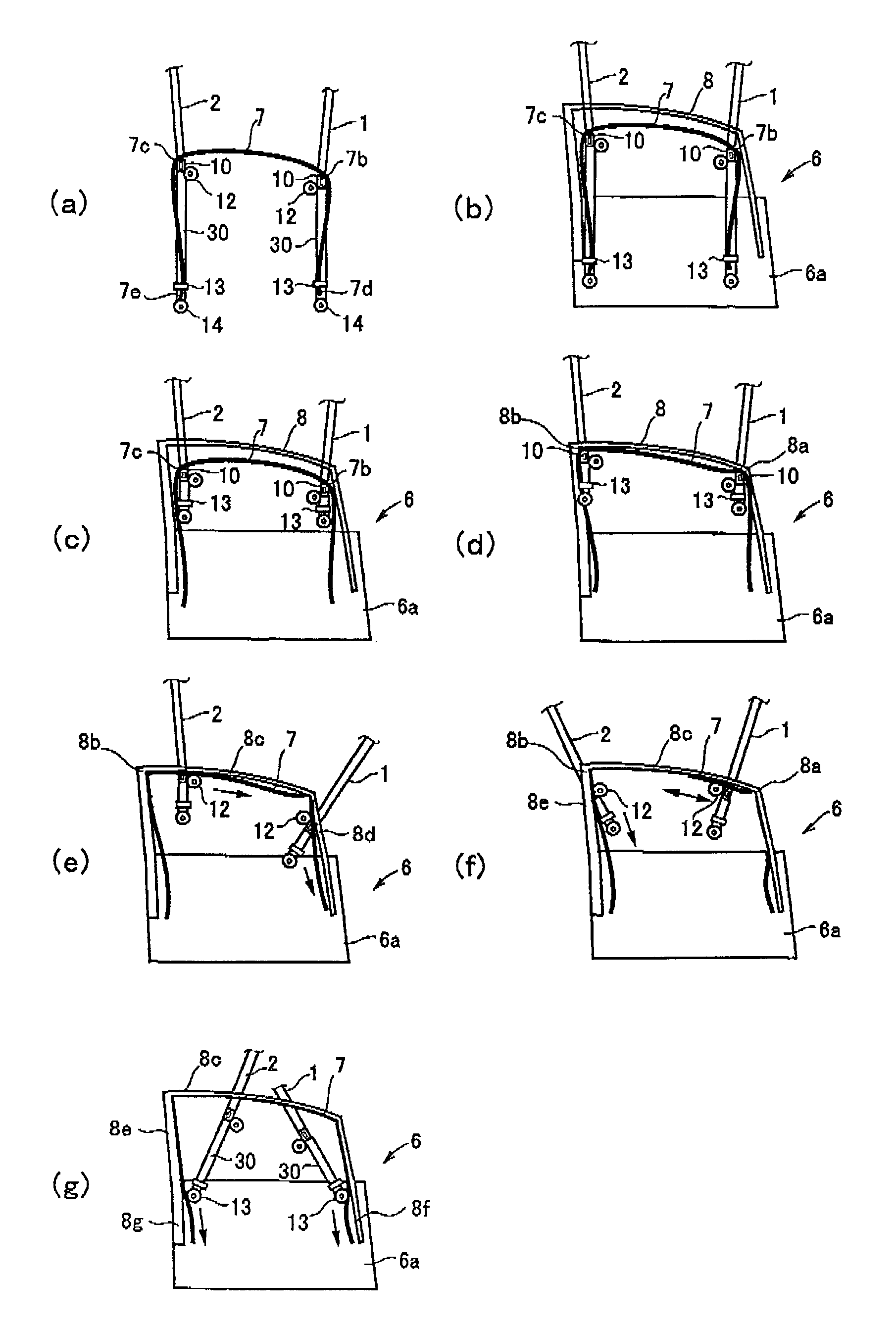
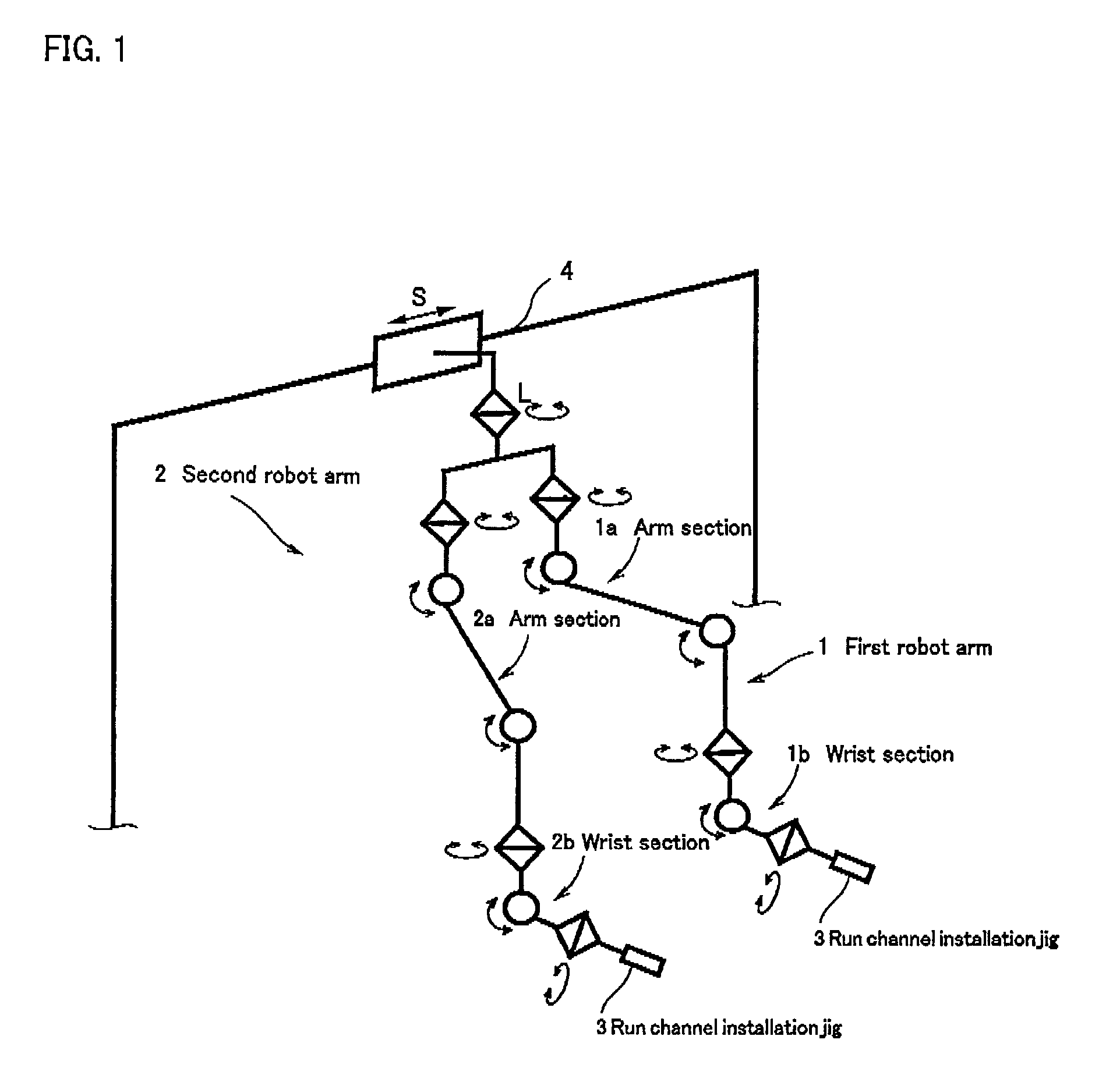
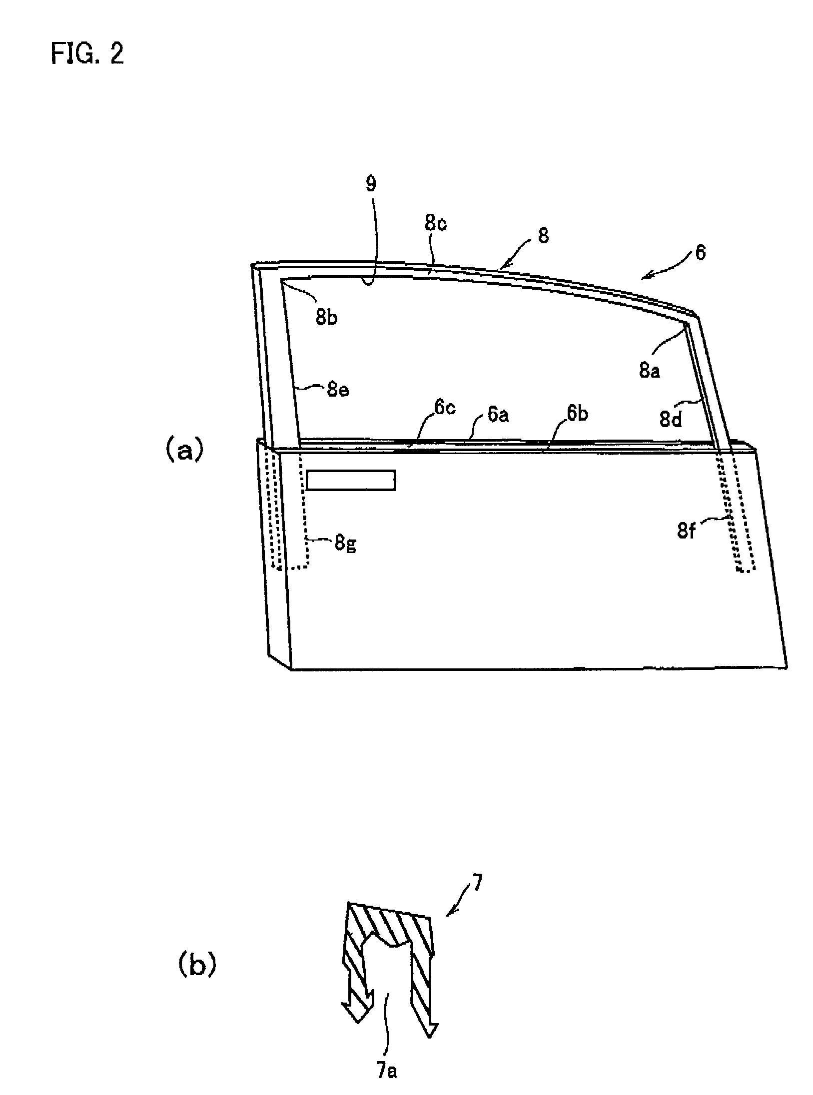
[0021]Embodiments of the present invention will be described with reference to the accompanying drawings below. Here, FIG. 1 is a schematic explanatory diagram of a run channel installation device for an automobile, FIG. 2 illustrate perspective views (a) of an automobile door and a sectional view and (b) of a run channel for an automobile door, FIG. 3 are schematic diagrams of a run channel installation jig, FIG. 4 are schematic diagrams of a first holding means and pressing means, FIG. 5 are schematic diagrams of an upper-sash roller, FIG. 6 are schematic diagrams of a slide means, FIG. 7 are schematic diagrams of second holding means and a lower-sash roller, and FIG. 8 are diagrams for describing operations of a lower-sash roller and a slide rail.

[0022]A device for installing a run channel for an automobile door related to the present invention comprises, as illustrated in FIG. 1, a first robot arm 1 and a second robot arm 2, the robot arms 1, 2 being a pair of robot arms with mu...


PUM

PropertyMeasurementUnit
degrees of freedomaaaaaaaaaa
widthaaaaaaaaaa
widthaaaaaaaaaa

Abstract

An automobile run channel installing method for installing a run channel in a sash of an automobile door is provided. The method involves setting a run channel to a conveyance device having only a pair of arms, the run channel having a concave section and only two corner sections; pushing both corner sections of the run channel into corner sections of an upper portion of the sash, respectively; pressing and fitting an upper-sash roller of the arm into the concave section of the run channel to move from the corner section of the upper sash; and pressing and fitting a lower-sash roller of the arm into the concave section of the run channel to move from a higher portion to a lower portion of a lower portion of the sash and to fit the run channel into the lower sash.

Description

TECHNICAL FIELD[0001]The present invention relates to an automobile run channel installing method for installing a run channel for an automobile on a sash of an automobile door, a device for installing a run channel for an automobile, and a soft member installation device for installing a soft member such as a run channel for an automobile door. The automobile door is shaped substantially concave in section and the soft member is installed in a concave groove of a member, substantially concave in section, such as a sash of an automobile door.BACKGROUND ART[0002]Conventionally, as a method for installing a run channel for an automobile door on a concave groove of sash of an automobile door, there is known a method for installing a run channel for an automobile door in a spatula section first with a seal rubber fitting jig composed of a spatula section formed in one end of a rod-like section bent to an L-shape, a pressing protruding section formed in a base of the spatula section and ...

Claims


Application Information

Patent Timeline
Patent Type & Authority Patents(United States)
IPC IPC(8): B23P11/02
CPCB23P19/047B25J5/02B25J9/0084B25J9/0087B60J10/0088Y10T29/53Y10T29/49945Y10T29/49998Y10T29/4987Y10T29/53657Y10T29/49826Y10T29/49872B60J10/45
Inventor KONDO, TOSHIYUKIKOMATSU, SAEKOSAKAMOTO, HIROAKI
Owner HONDA MOTOR CO LTD
Why Eureka
Try Eureka