
Method for installing run channel for automobile, device for installing run channel for automobile, and soft member installation device

a technology for installing run channels and automobiles, which is applied in the direction of programmed manipulators, manufacturing tools, transportation and packaging, etc., can solve the problems of contributing to man-hour reduction, achieve accurate and automatic installation, and reduce the burden of large amoun

Inactive Publication Date: 2009-06-04
HONDA MOTOR CO LTD
View PDF3 Cites 0 Cited by
  • Summary
  • Abstract
  • Description
  • Claims
  • Application Information

AI Technical Summary

Benefits of technology

[0009]According to the present invention, a run channel for an automobile door being a long soft object can be installed accurately and automatically in a sash of an automobile door. In addition, improvement and stabilization in quality of installation of a run channel for an automobile door can be attained.
[0010]Also, according to the present invention, with an operation of a roller with deflection of a supporting member, a soft member such as a run channel for an automobile door being a long soft object can be installed accurately and automatically in a concave groove present in a substantially concave member in section such as a sash of an automobile door without causing control means to bear a large burden. In addition, improvement and stabilization in quality of installation of a soft member such as a run channel for an automobile door in a concave groove can be attained.

Problems solved by technology

However, the method for installing a run channel for an automobile door disclosed in Patent Literature 1 has a problem in that it does not contribute to man-hour reduction since a worker uses a seal rubber fitting jig to install a run channel for an automobile door in a concave groove of a sash of an automobile door.

Method used


Image

  • Method for installing run channel for automobile, device for installing run channel for automobile, and soft member installation device
  • Method for installing run channel for automobile, device for installing run channel for automobile, and soft member installation device
  • Method for installing run channel for automobile, device for installing run channel for automobile, and soft member installation device

Examples


Embodiment Construction

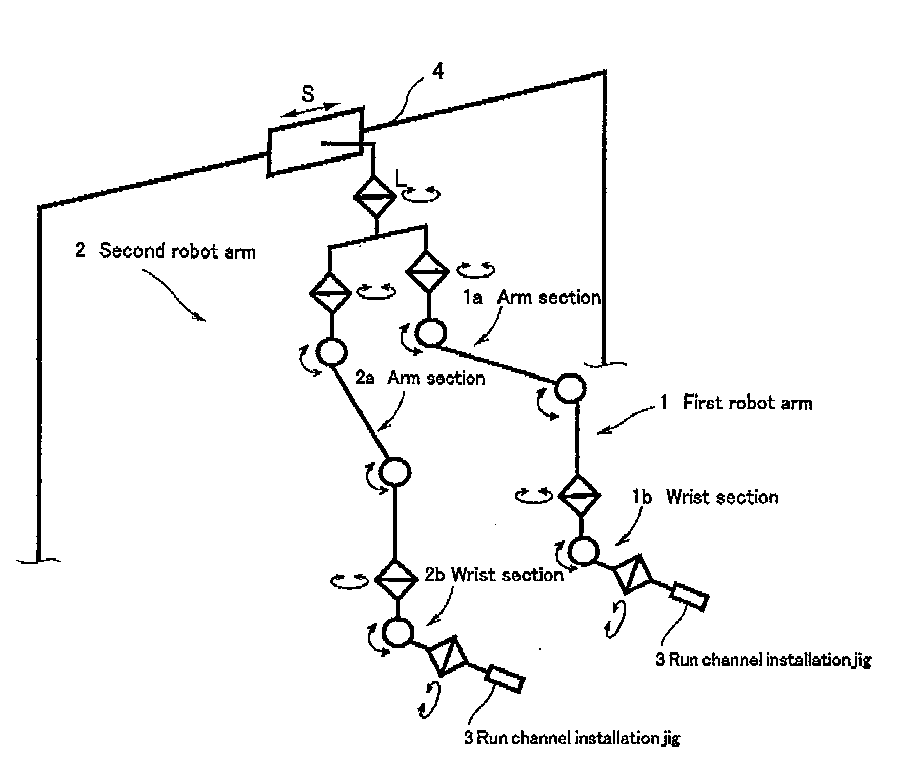
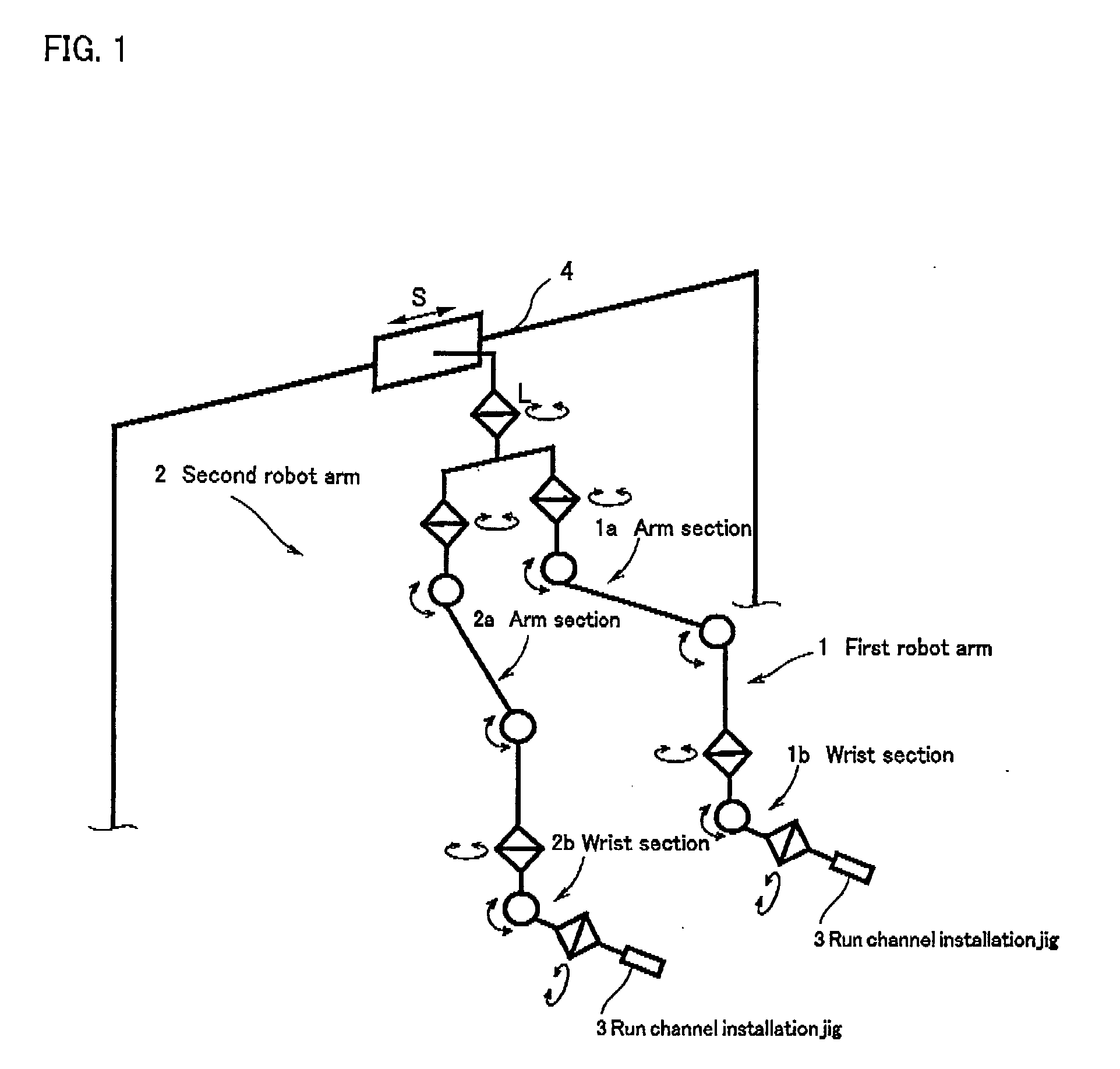
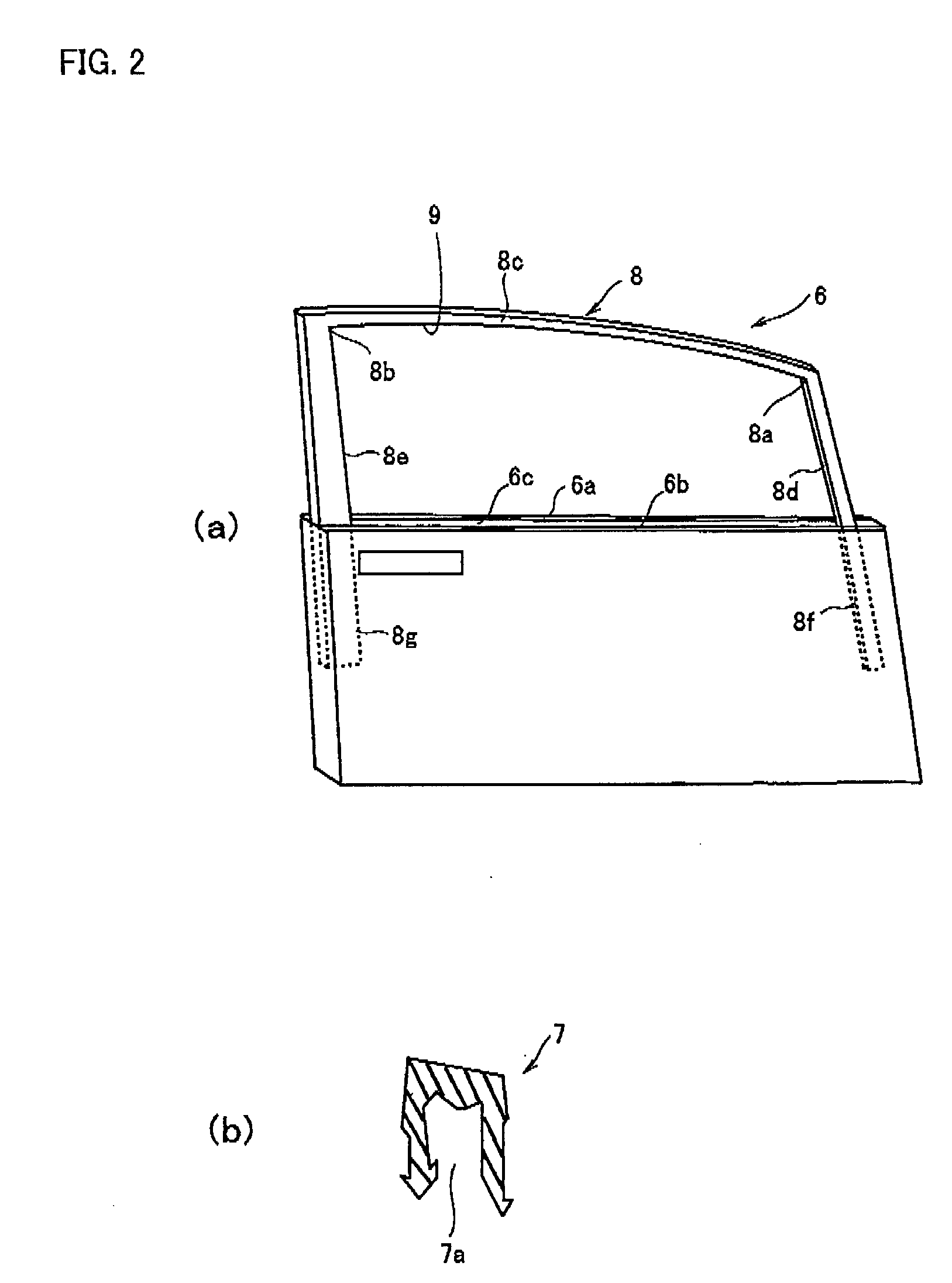
[0021]Embodiments of the present invention will be described with reference to the accompanying drawings below. Here, FIG. 1 is a schematic explanatory diagram of a run channel installation device for an automobile, FIG. 2 illustrate perspective views (a) of an automobile door and a sectional view and (b) of a run channel for an automobile door, FIG. 3 are schematic diagrams of a run channel installation jig, FIG. 4 are schematic diagrams of a first holding means and pressing means, FIG. 5 are schematic diagrams of an upper-sash roller, FIG. 6 are schematic diagrams of a slide means, FIG. 7 are schematic diagrams of second holding means and a lower-sash roller, and FIG. 8 are diagrams for describing operations of a lower-sash roller and a slide rail.

[0022]A device for installing a run channel for an automobile door related to the present invention comprises, as illustrated in FIG. 1, a first robot arm 1 and a second robot arm 2, the robot arms 1, 2 being a pair of robot arms with mu...


PUM

PropertyMeasurementUnit
degrees of freedomaaaaaaaaaa
widthaaaaaaaaaa
widthaaaaaaaaaa

Abstract

A versatile device for installing a run channel for an automobile, capable of contributing to man-hour reduction and being used for multiple models. A device for installing a run channel on a sash of an automobile door, the device being composed of a robot having a pair of arms and a run channel installation jig (3) provided on each of the arms. The run channel installation jig (3) has a first holding means (10) for holding both corner sections of the run channel, a pressing means (11) for pressing and fitting both corner sections of the run channel held by the first holding means (10) into corner sections of an upper sash, a rotatable upper-sash roller (12) pressing and fitting the run channel into the upper sash, a second holding means (13) for holding both end sections of the run channel, a rotatable lower-sash roller (14) for pressing and fitting the run channel into a lower sash, and a slide means (15) for arbitrarily setting the distance of the second holding means (13) and the lower-sash roller (14) relative to the first holding means (10).

Description

TECHNICAL FIELD [0001]The present invention relates to an automobile run channel installing method for installing a run channel for an automobile on a sash of an automobile door, a device for installing a run channel for an automobile, and a soft member installation device for installing a soft member such as a run channel for an automobile door. The automobile door is shaped substantially concave in section and the soft member is installed in a concave groove of a member, substantially concave in section, such as a sash of an automobile door.BACKGROUND ART [0002]Conventionally, as a method for installing a run channel for an automobile door on a concave groove of sash of an automobile door, there is known a method for installing a run channel for an automobile door in a spatula section first with a seal rubber fitting jig composed of a spatula section formed in one end of a rod-like section bent to an L-shape, a pressing protruding section formed in a base of the spatula section an...

Claims


Application Information

Patent Timeline
Patent Type & Authority Applications(United States)
IPC IPC(8): B23P19/02
CPCB23P19/047B25J5/02B25J9/0084B25J9/0087B60J10/0088Y10T29/53Y10T29/49945Y10T29/49998Y10T29/4987Y10T29/53657Y10T29/49826Y10T29/49872B60J10/45
Inventor KONDO, TOSHIYUKIKOMATSU, SAEKOSAKAMOTO, HIROAKI
Owner HONDA MOTOR CO LTD
Learn More