Whisk, in particular for culinary use

a technology for whisks and whisks, which is applied in the field of whisks, can solve the problems of unusable whisks, poor suited for whisk use, and whisk handle contact, and achieve the effect of convenient hanging and convenient us

Inactive Publication Date: 2011-10-11
MASTRAD
View PDF44 Cites 6 Cited by
  • Summary
  • Abstract
  • Description
  • Claims
  • Application Information

AI Technical Summary

Benefits of technology

[0007]In view of the foregoing, it is an object of the present invention to provide a whisk that includes a mechanism allowing it to be easily hung from the edge of a container, but which is safe and easy to use.
[0009]The whisk having the previously described structure may be stably placed inside a container without the risk that the whisk will slide into the container. The whisk may be attached to edges of different thicknesses. The whisk may further be attached to containers having pronounced or reinforced rims. Still further, the whisk may be attached to various containers regardless of the particular materials from which they are made and regardless of the particular shape or angle of the edges of the containers, including the particular angle formed with the vertical axis in the area of the container's rim.

Problems solved by technology

One problem with placing the whisk outside the container, such as on a plate, is that mixed ingredients remaining on the whisk's active part drip off onto the plate and, thus, become unusable.
If the whisk is placed within the bowl, it is likely that the whisk will slide down (i.e., fall over) thereby causing the whisk's handle to contact the ingredients being mixed.
Unfortunately, such items generally are intended for utensils that have long thin handles, such as serving utensils, and therefore are poorly suited for use with whisks.
Moreover, these devices often are not in easy reach of a user, and sometimes are simply forgotten about or get lost.
Still further, using these types of supporting elements, including positioning them on the container or bowl and their subsequent removal after use, complicates and extends the mixing operation.
However, such hooks generally are designed for utensils with long thin handles and typically only for those utensils that are used to serve food, such as ladles and spoons.
Unfortunately, hooks are ill-suited for whisks for at least two reasons.
First, whisks generally have a relatively short handle and thus it is too easy for the user to grab the hook, and thus hurt oneself, when grabbing the whisk.
Second, a whisk is used to stir ingredients within a bowl or other receptacle and thus requires strong, fast movement, which also may result in injury to the user during use if an open-ended hook is placed on the whisk's handle.

Method used


Image

  • Whisk, in particular for culinary use
  • Whisk, in particular for culinary use
  • Whisk, in particular for culinary use

Examples


Embodiment Construction

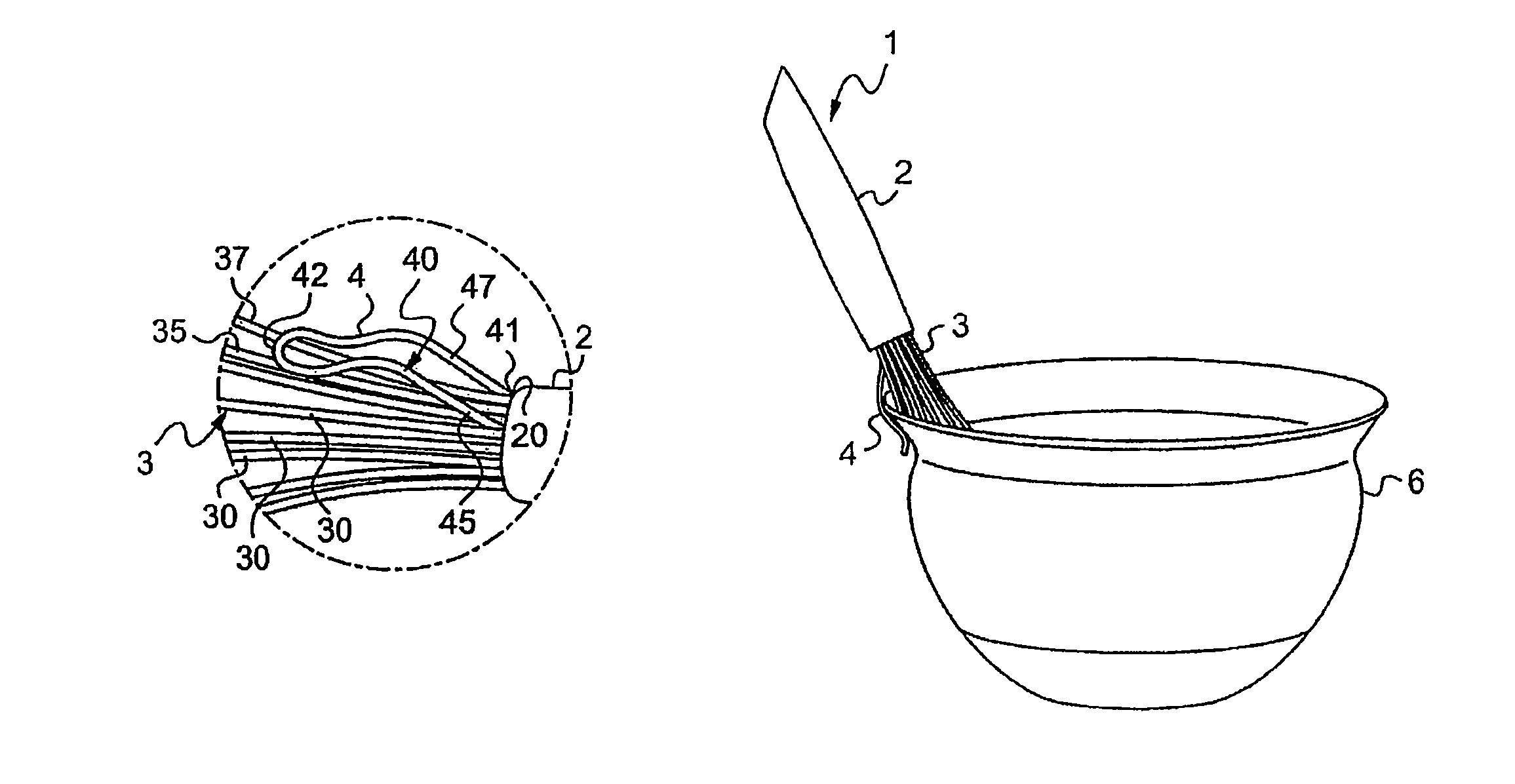
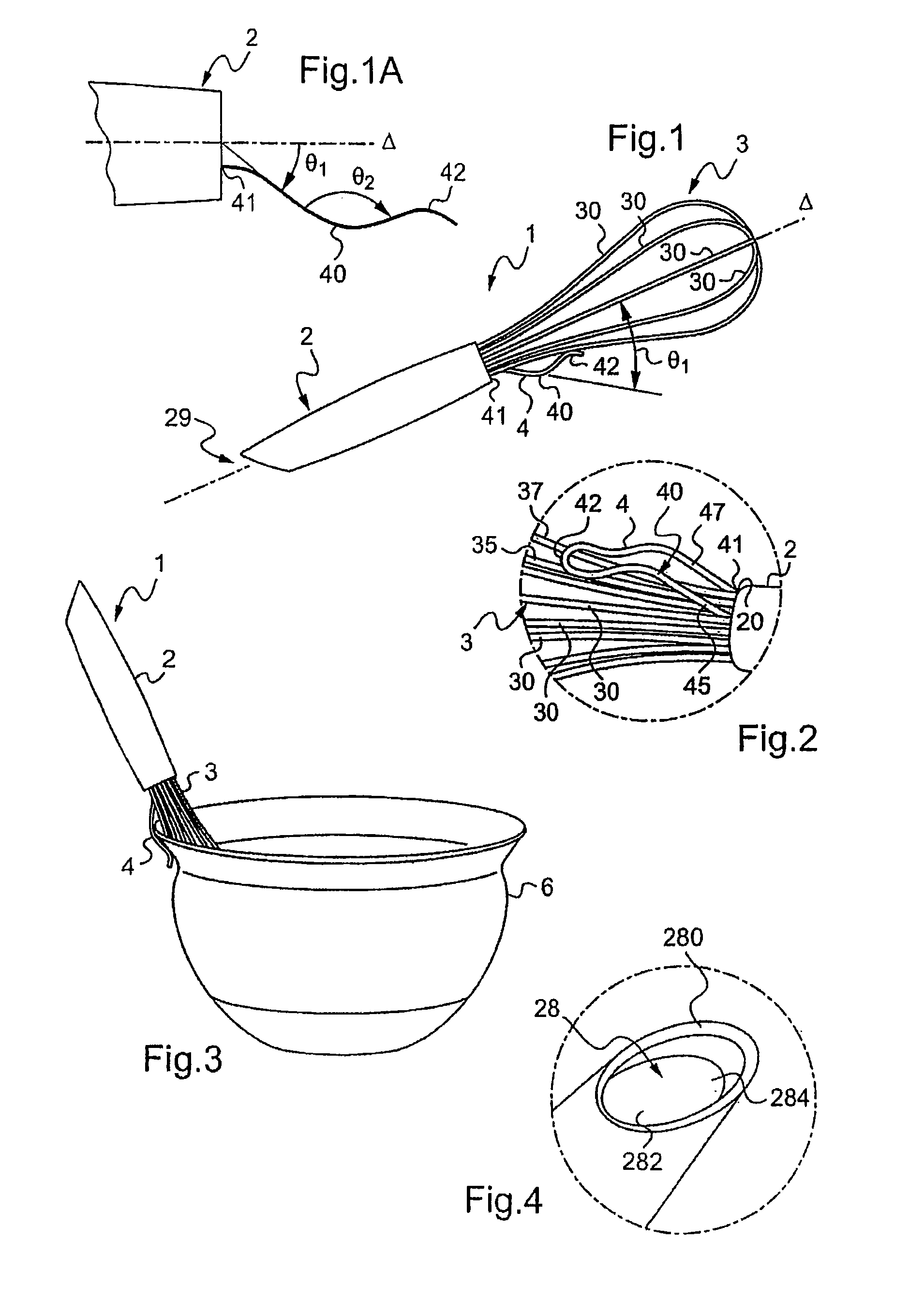
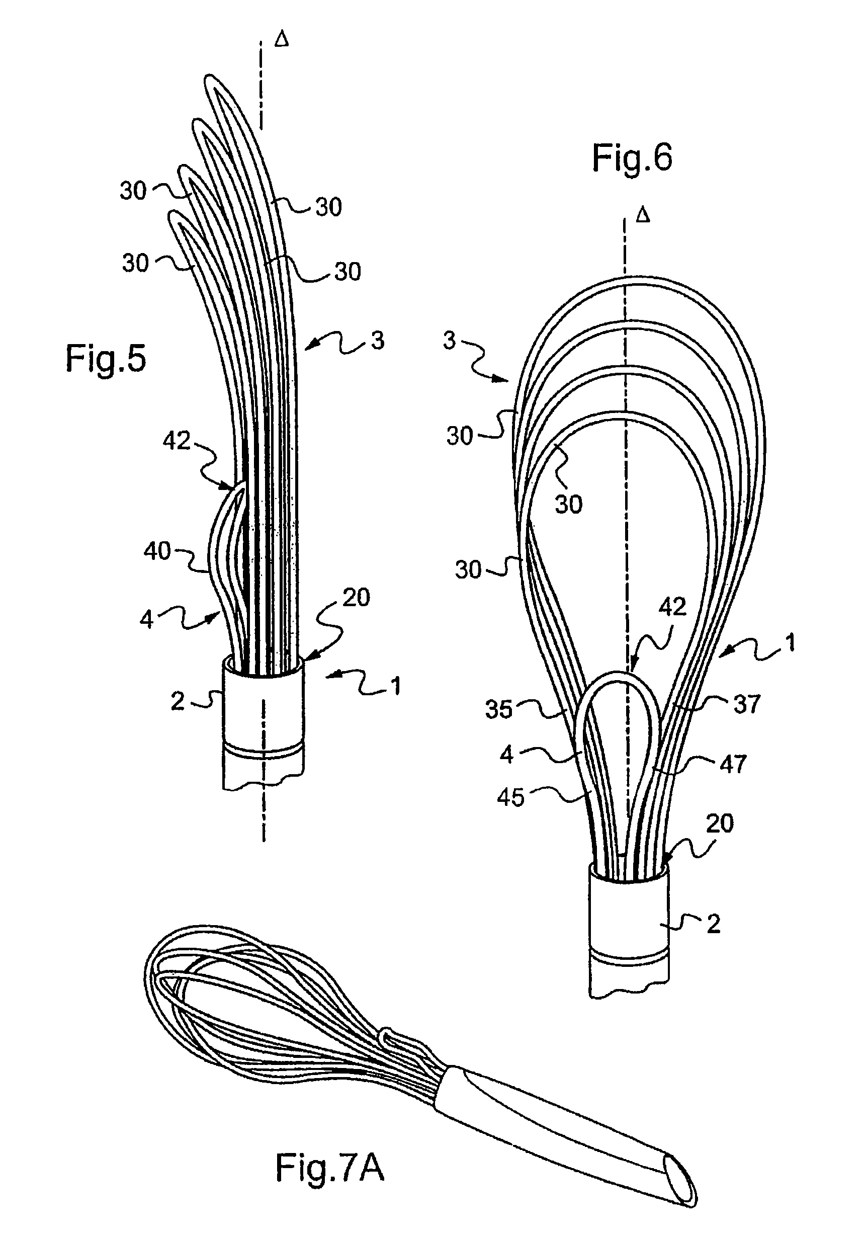
[0037]FIG. 1 schematically illustrates a kitchen utensil 1 in accordance with the present invention. Kitchen utensil 1, in its general sense, includes a handle and an active part. In the exemplary illustration, kitchen utensil 1 is a whisk and, accordingly, the active part is the bundle of shafts mounted on the utensil's handle. As shown in FIG. 1, the whisk generally has a pear-shaped design, and is particularly adapted for optimizing the mixing of ingredients.

[0038]As shown in FIG. 1, whisk includes a handle 2 that extends along an axis Δ. The active part includes a bundle of semi-rigid shafts that are generally pear-shaped in design. During use, the user grasps handle 2 and utilizes the whisk in the ordinary manner. Preferably, the bundle 3 of shafts is adapted to mix a variety of products and ingredients, including liquids, such as sauces, liquid-solid combinations, and solids, such as soft dough.

[0039]As shown in FIG. 1, the bundle 3 has a set of shafts 30, with each shaft 30 h...


PUM


Abstract

A whisk, in particular for culinary use, having a handle and an active part with a predominately pear-shaped general shape and that is mounted on the handle. The whisk also includes an attachment clip mounted on the handle and that has a spatula-shaped end part at its free end. The attachment clip rests on the active part of the whisk and has an angled shape with a concavity that is turned towards the inside of the whisk.

Description

CLAIM OF PRIORITY[0001]This application claims the benefit of French Patent Applications No. 06 / 07387, filed on Aug. 18, 2006, the entire contents of which are hereby incorporated by reference herein.FIELD OF THE INVENTION[0002]The present invention relates to whisks, in particular for culinary use, for mixing ingredients in a container, for example, a mixing bowl.BACKGROUND OF THE INVENTION[0003]Conventional whisks include a handle and a bundle of shafts, which make up an “active part” that extends from the handle. The active part generally is pear-shaped and designed to optimize mixing ingredients.[0004]After a user discontinues using a conventional whisk, the user generally places the whisk within the mixing bowl, rests the whisk across the top surface of the bowl, or places the whisk on a plate of some sort. One problem with placing the whisk outside the container, such as on a plate, is that mixed ingredients remaining on the whisk's active part drip off onto the plate and, thu...

Claims


Application Information

Patent Timeline
Patent Type & Authority Patents(United States)
IPC IPC(8): A47J43/10
CPCA47J43/1093A47J43/287
Inventor LION, MATHIEU
Owner MASTRAD
Why Eureka
Try Eureka