
Toilet clog clearance device

a technology for clearing clogs and toilets, which is applied in water installations, cleaning processes and apparatuses, constructions, etc., can solve the problems of complex design and unfavorable use of tools, and achieve the effect of convenient hanging

Active Publication Date: 2017-04-25
BRUMMER TOBY
View PDF16 Cites 2 Cited by
  • Summary
  • Abstract
  • Description
  • Claims
  • Application Information

AI Technical Summary

Benefits of technology

[0008]It is a second object to provide a device that does not splatter water, feces, or urine to the floor of the bathroom or on the clothing of the user, when unclogging a toilet.
[0009]It is a third object to provide an unclogger that is light in weight and as such can be used by persons of all ages.
[0010]It is a fourth object to provide a device that can be easily hung on a hook for storage until the occasion when needed.

Problems solved by technology

The plunger is messy spills water or urine or feces fluid on the floor, perhaps on the clothing of the user, and the tool is not fun to use.
Prior art tools that are less common include the “Splunger”, a combination tool, disclosed and claimed in US Patent Publication 2006 / 0260077 of Wilson, which is quite complex in design.

Method used


Image

  • Toilet clog clearance device
  • Toilet clog clearance device
  • Toilet clog clearance device

Examples


first embodiment

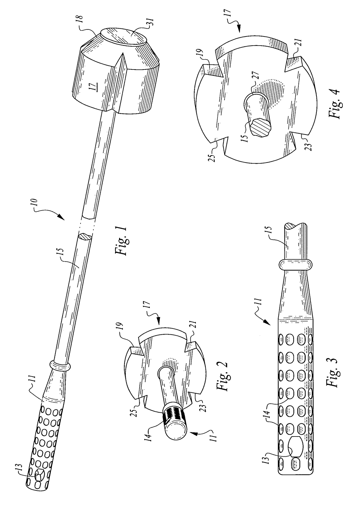
[0023]Let us turn first to FIG. 1 which is a perspective view of the The device 10 is seen to have 3 portions, a handle 11 which has a distal and a proximal end, an elongated shaft second portion 15 which also has distal and proximal ends and an operative head portion 17 formed of a semi-rigid bullet shaped section 18, attached at its rear to the distal end of the shaft and a rigid cap disposed in the forward end of the bullet shaped section to inhibit deformation of the foam head. The external surface of the cap is generally flat, but may be slightly convex.

[0024]The handle portion 11 is an elongated rod of a diameter of about 1 inch for easy gripping by young and old alike, and the handle has at its proximal end, a hole either round of about ¼ inch diameter or an elongated slot of about ¼ by ⅝ths inch to permit the unit to be easily hung on a hook in storage awaiting the infrequent occasion when use is required. The handle may have a rubber coating thereon to enhance grippability...

second embodiment

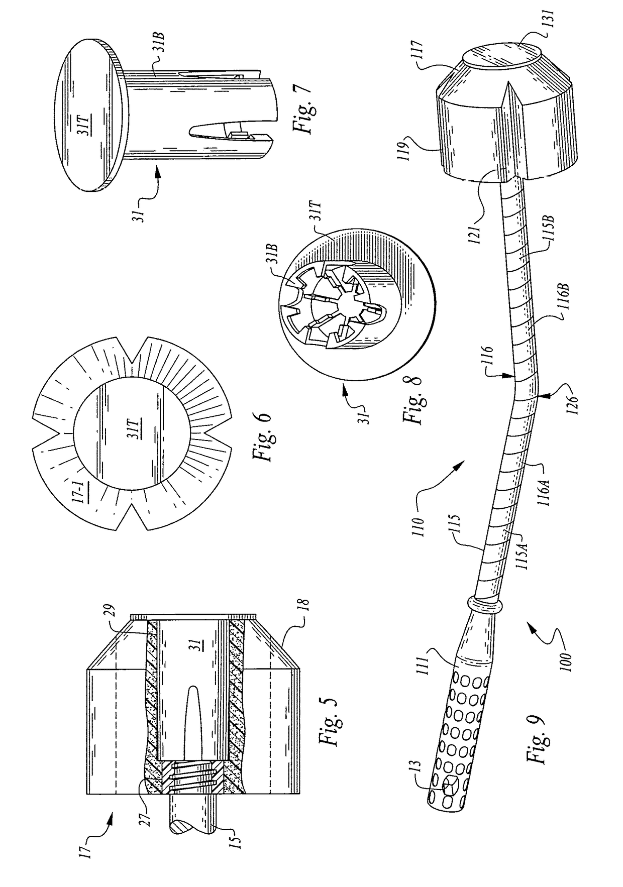
[0038]It should be noted that either handle 11 or handle 111 can be substituted for the other and that embodiments with a straight or canted (bent) shaft with either handle are contemplated. Also the employment of a slot in the handle of the second embodiment is also within the scope of this invention.

[0039]While closed cell polyethylene foam has been mentioned, any semi-rigid closed cell polymeric foam can be employed for the material of the head such as polyurethane closed cell foam. The cap, 131, and 31 is made of any high impact plastic such as styrene.

[0040]A typical unit will have a head approximately three inches long by three inches wide with V-grooves of about ¼ inch to ½ inch wide. The shaft can vary from 12 to 18 inches long by about ½ to 1 inch in diameter, with a handle of six to 8 inches long and of a slightly larger diameter than the shaft for ease of use. The cap in the nose of the bullet shaped head should be about 1.5 inches in diameter.


PUM


Abstract

This toilet unclogging tool has a handle attached at the proximal end of, a shaft, either straight or bent, and a bullet shaped head portion, attached at the distal end of the shaft, which head is made of a semi-rigid material such as closed cell polyethylene foam. The head has a series of grooves, usually four of a V-shape, along the length thereof to permit fluid to pass there through when one attempts to push a blockage forward over the trap of a toilet. A rigid cap having a flat face is disposed into the forward end of the head to enhance the ability of the device to push a clog without deforming the head.

Description

FIELD OF INVENTION[0001]This invention relates to devices used for forcing toilet paper and other materials that clog a toilet forward to the drain to unclog the toilet.BACKGROUND OF THE INVENTION[0002]People of all ages, from little toddlers to senior citizens have from time to time clogged toilets by placing non-biodegradable items in the toilet and then attempting to flush the toiler. These items can range from excess toilet paper, to paper towels to toy soldiers, to Lego® pieces, to sanitary napkins, to cell phones, and every other imaginable item.[0003]The most common tools used for unclogging a toilet are a snake, which requires a bit of expertise and which tool is usually not found in the household, and a plunger which is a rubber deformable cup mounted on a handle, which cup fits over the throat of the toilet trap. A partial vacuum is formed so that the change in pressure upon release of the cup over the throat of the trap will force the blockage up and over the trap. The pl...

Claims


Application Information

Patent Timeline
Patent Type & Authority Patents(United States)
IPC IPC(8): E03C1/302B08B9/02B08B9/027E03C1/30E03D9/00A47K11/10
CPCB08B9/02B08B9/027E03C1/30A47K11/10E03D9/00
Inventor BRUMMER, TOBY
Owner BRUMMER TOBY
Learn More