Pulse combustion dryer apparatus and methods

a dryer and pulse technology, applied in the direction of combustion types, lighting and heating apparatus, furnaces, etc., can solve the problems of mechanical valves that are prone to failure, require maintenance, and are mechanically complex

Inactive Publication Date: 2011-10-18
PULSE HLDG
View PDF14 Cites 11 Cited by
  • Summary
  • Abstract
  • Description
  • Claims
  • Application Information

AI Technical Summary

Problems solved by technology

However, mechanical valves may be mechanically complex, may require maintenance, and may be prone to failure due to, for example, mechanical stresses, thermal stresses, fatigue, and corrosion by the heated combustion products.
However, pulse combustion dryers that use fluid diodes to control backflow of heated combustion products through the air inlet may still experience some backflow of heated combustion products through the air inlet.

Method used


Image

  • Pulse combustion dryer apparatus and methods
  • Pulse combustion dryer apparatus and methods
  • Pulse combustion dryer apparatus and methods

Examples


Embodiment Construction

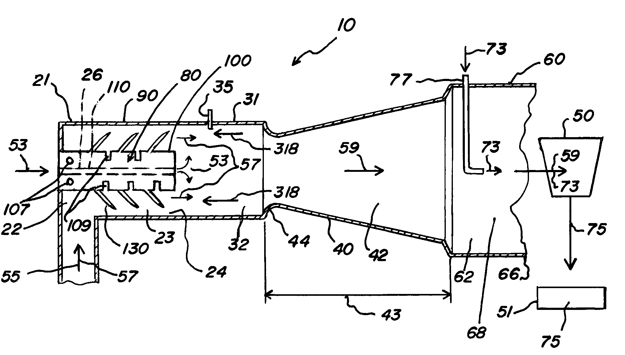
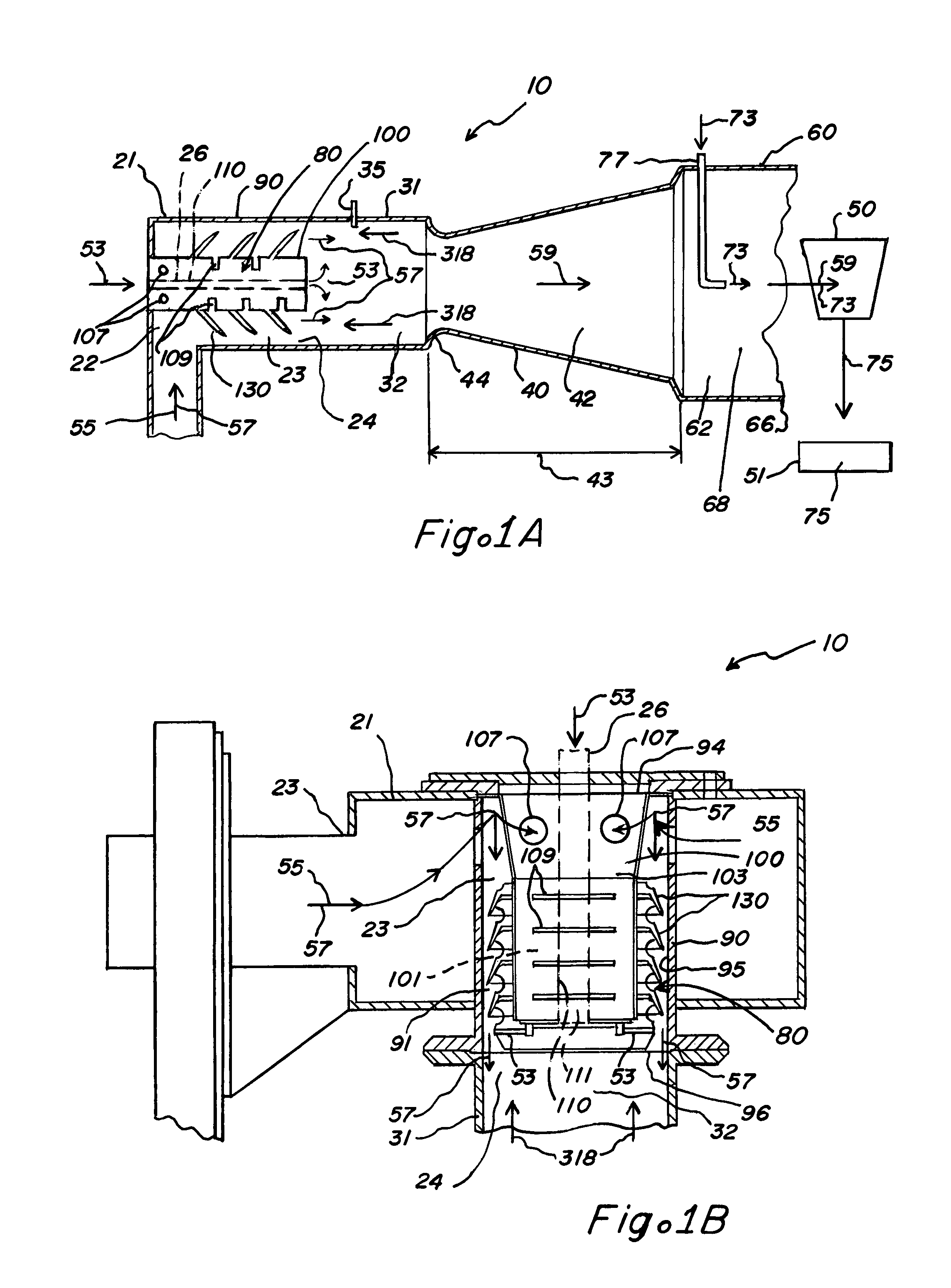
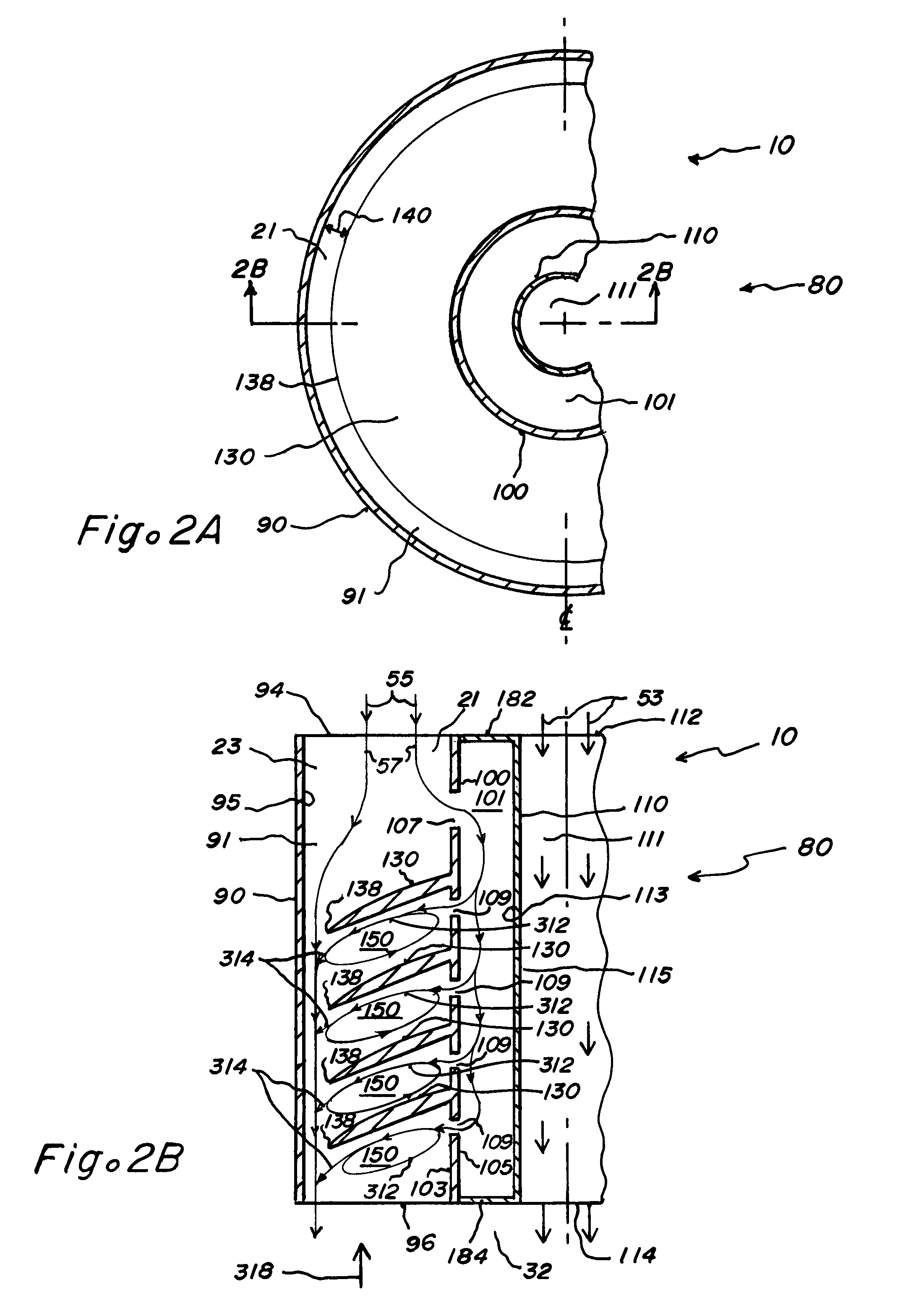
[0025]The present inventions provide a pulse combustion dryer apparatus 10 for the drying of a dryer feed material 73. The pulse combustion dryer apparatus 10 may include a combustor 31, an air inlet 21, a fluid diode 80, and a tailpipe 40. The combustor 31 defines a combustion chamber 32, and the air inlet 21 is in fluid communication with the combustion chamber 32 to communicate air 55 into the combustion chamber 32. The fluid diode 80 is included within the air inlet 21 to regulate flow through the air inlet by allowing airflow 57 through the air inlet 21 into the combustion chamber 32 and generally preventing backflow 318 from the combustion chamber 32 through the air inlet 21. The pulse combustion dryer 10 may include the tailpipe 40 that defines a tailpipe passage 42 that fluidly communicates with the combustion chamber 32. The combustion chamber 32 is configured to receive a pulse of airflow 57 admitted through the air inlet 21 and a pulse of fuel 53, and to ignite periodical...


PUM


Abstract

The present inventions relate to pulse combustion dryer apparatus and associated methods. The pulse combustion dryer apparatus may include a combustor that defines a combustion chamber that is in fluid communication with a tailpipe passage defined by a tailpipe. An air inlet communicates air into the combustion chamber through an air inlet passage. A fluid diode disposed within the air inlet passage allows airflow into the combustion chamber through the air inlet passage, and may generally prevent backflow of heated combustion products from the combustion chamber through the air inlet passage.

Description

BACKGROUND OF THE INVENTION[0001]1. Field of the Invention[0002]The present inventions relate to apparatus and methods for drying materials, and, more particularly, to apparatus and methods for pulse combustion drying.[0003]2. Background of the Related Art[0004]The typical pulse combustion dryer includes a combustor connected to a tailpipe. The combustor defines a combustion chamber. Fuel and air may be admitted into the combustion chamber through an air inlet and fuel inlet, respectively, and the resulting fuel-air mixture periodically ignited to propel pulses of heated combustion products through the tailpipe from the combustion chamber. The term “pulse combustion” thus originates from the periodic ignition of solid, liquid, or gaseous fuel to generate pulses of heated combustion products, in contrast to the continuous ignition of fuel in conventional dryers. The material to be dried may be introduced into the pulses of heated combustion products typically in the tailpipe and / or i...

Claims


Application Information

Patent Timeline
Patent Type & Authority Patents(United States)
IPC IPC(8): F26B3/06F26B17/10F23C15/00
CPCF23C15/00F23D14/82F26B23/026
Inventor GROBLER, MARIUSMIRKO, DAVID A.REHKOPF, JAMES A.
Owner PULSE HLDG
Why Eureka
Try Eureka