Wind turbine generator system and method of controlling output of the same

a generator system and wind turbine technology, applied in the direction of electric generator control, machine/engine, dynamo-electric converter control, etc., can solve the problems of power factor deviating from a predetermined range, and the operation of wind turbines must be stopped

Active Publication Date: 2011-10-18
MITSUBISHI HEAVY IND LTD
View PDF10 Cites 4 Cited by
  • Summary
  • Abstract
  • Description
  • Claims
  • Application Information

AI Technical Summary

Benefits of technology

It is an object of the present invention to provide a wind turbine generator system that can supply, to the utmost extent, reactive power according to a demand from a utility grid side while maintaining the power factor within a certain range and to provide a method of controlling the output of the same.
With such a structure, the constant-reactive-power regulation can be performed within a range not deviating from the operating region, and reactive power of a certain level or more demanded by the utility grid side can be provided to the utmost extent. Furthermore, when a deviation from the operating region occurs, the constant-reactive-power regulation is switched to the constant-power-factor regulation. Consequently, a large deviation from the operating region can be avoided, and the wind turbine can be continuously operated. Accordingly, it is possible to avoid halting the operation of the wind turbine, thereby suppressing a decrease in power generation efficiency.

Problems solved by technology

However, for example, in order to supply reactive power in a certain level or more even when the level of the active power is significantly decreased due to wind or other conditions, it is predicted that the power factor will deviate from a predetermined range that is required by the utility grid side.
One concern in such a case, for example, is the risk of causing a situation where the operation of a wind turbine must be stopped.

Method used


Image

  • Wind turbine generator system and method of controlling output of the same
  • Wind turbine generator system and method of controlling output of the same
  • Wind turbine generator system and method of controlling output of the same

Examples


Embodiment Construction

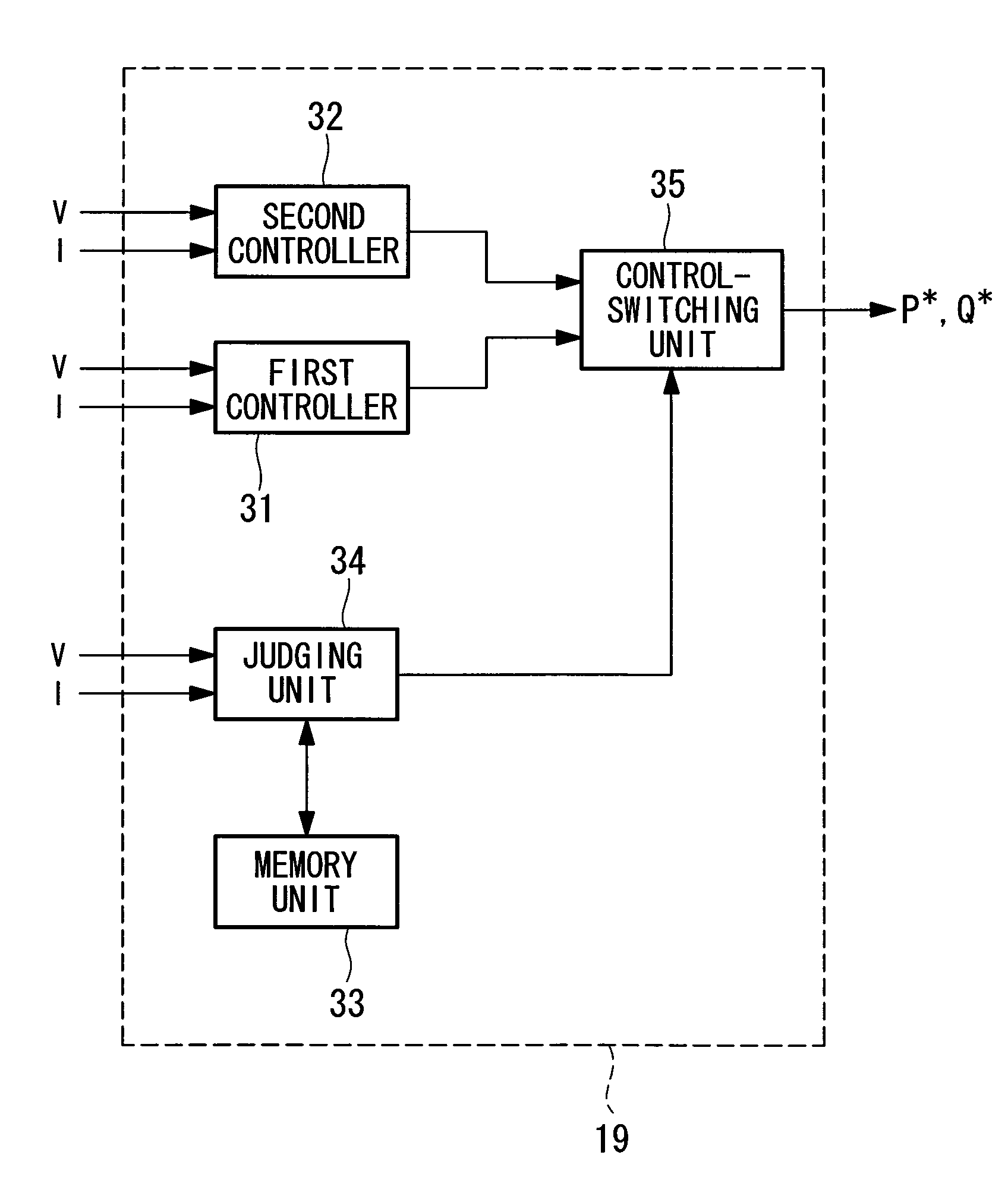
An embodiment of the wind turbine generator system according to the present invention will be described below with reference to the drawings.

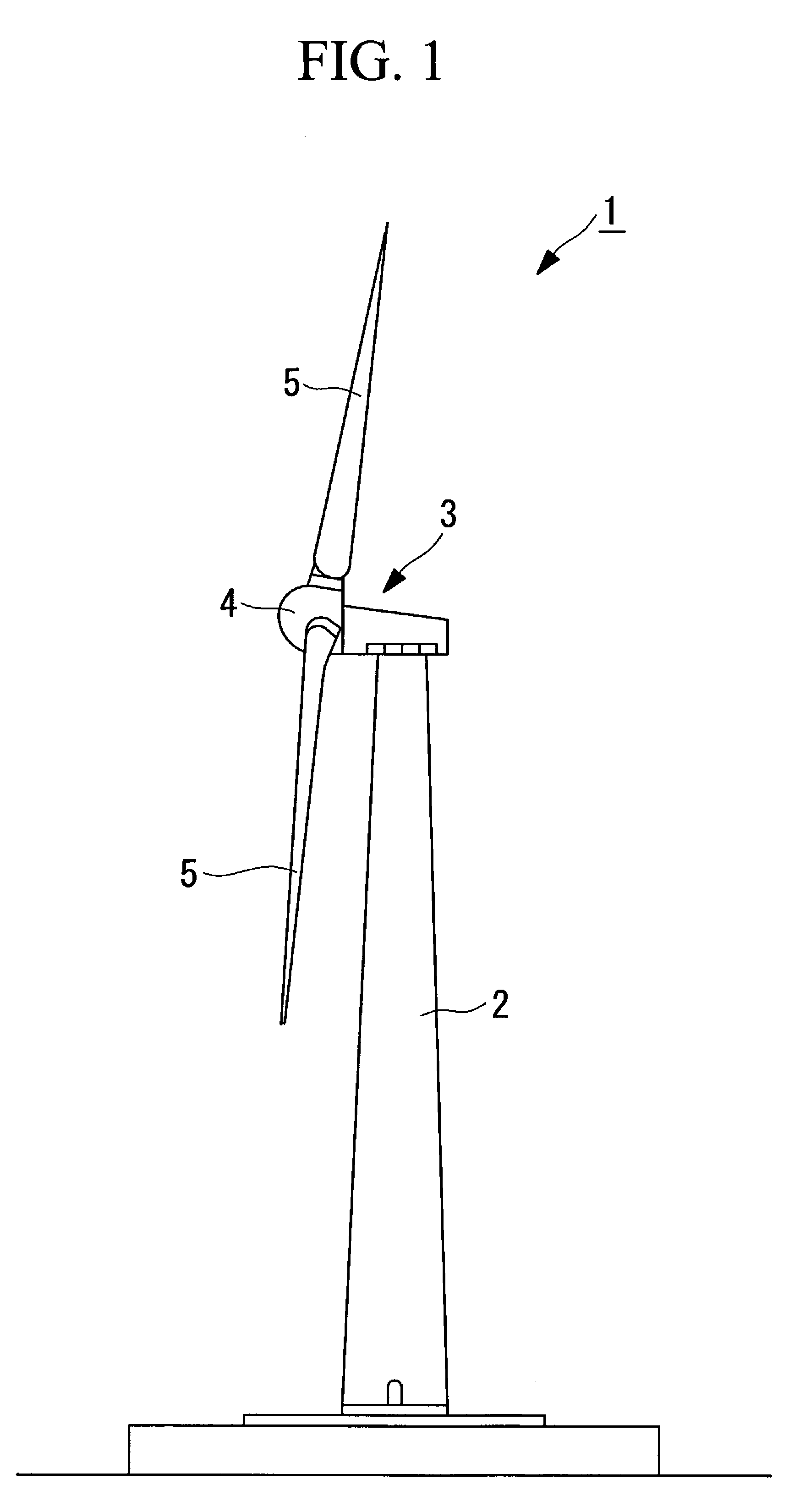
FIG. 1 is a drawing illustrating the overall configuration of a wind turbine generator system. As shown in FIG. 1, the wind turbine generator system 1 includes a tower 2, a nacelle 3 mounted atop the tower 2, and a rotor head 4 provided on the nacelle 3 so as to be rotatable around an approximately horizontal axis. The rotor head 4 is fitted with three wind turbine blades 5 that are arranged radially around the rotation axis thereof. As a result, the force of wind blowing against the wind turbine blades 5 from the direction of the rotation axis of the rotor head 4 is converted into motive energy causing the rotor head 4 to rotate around the rotation axis. This motive energy is converted into electrical energy by the generator disposed in the nacelle 3.

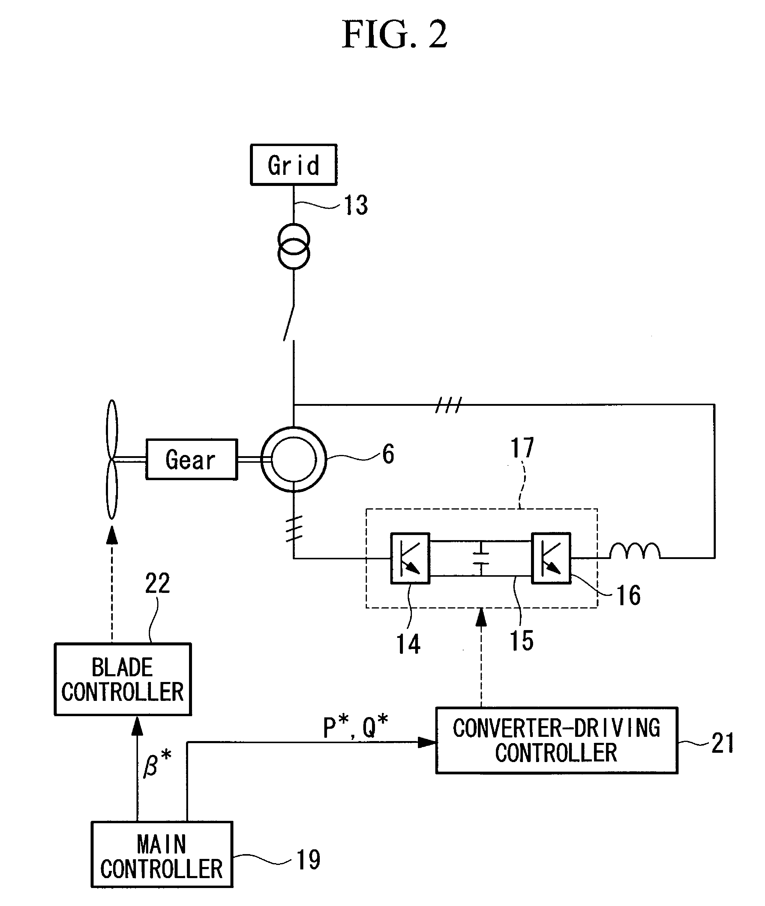
FIG. 2 is a block diagram illustrating an example of the configuration of the generator 6 and ...


PUM


Abstract

It is an object to supply, to the utmost extent, reactive power according to a demand of a utility grid side while maintaining the power factor within a predetermined range. The wind turbine generator system includes a main controller 19. The controller 19 includes a first controller 31 performing constant-reactive-power regulation, a second controller 32 performing constant-power-factor regulation, a judging unit 34 for judging whether a present operating condition is within a predetermined operating region, and a control-switching unit 35 for switching from the first controller 31 to the second controller 32 when the first controller 31 is performing the constant-reactive-power regulation and the judging unit 34 detects a deviation from the operating region.

Description

CROSS-REFERENCE TO RELATED APPLICATIONSThe present application is based on International Application No. PCT / JP2009 / 050093, filed Jan. 7, 2009, and priority is hereby claimed under 35 USC §119 based on this application. This application is hereby incorporated by reference in its entirety into the present application.TECHNICAL FIELDThe present invention relates to a wind turbine generator system and a method of controlling the output of the same.BACKGROUND ARTRecently, in fields such as wind turbine generator systems, it is required to ensure a power factor within a predetermined range, when electric power is supplied to a utility grid from a wind turbine generator system, in view of stabilizing the power supply in the utility grid.Accordingly, for example, to keep a constant power factor, constant-power-factor regulation is performed for controlling the active power and the reactive power (for example, Japanese Unexamined Patent Application, Publication No. 2001-268805).Patent Docum...

Claims


Application Information

Patent Timeline
Patent Type & Authority Patents(United States)
IPC IPC(8): F03D9/00H02P9/04H02P9/00
CPCH02P9/007H02P9/48H02P2101/15
Inventor YASUGI, AKIRA
Owner MITSUBISHI HEAVY IND LTD
Why Eureka
Try Eureka