Identifying spurious regions in a video frame

a video frame and spurious region technology, applied in image analysis, instruments, computing, etc., can solve problems such as video processing system waste of data processing and memory resources, and introduce system nois

Active Publication Date: 2011-10-18
BRITISH TELECOMM PLC
View PDF12 Cites 8 Cited by
  • Summary
  • Abstract
  • Description
  • Claims
  • Application Information

AI Technical Summary

Benefits of technology

[0028]According to a further aspect of the invention, there is provided video processing apparatus comprising: an input for receiving frames of a video sequence; an object queue arranged to store data representing objects identified in one or more frames and, associated with each object, a status parameter representing one of a plurality of predetermined states; video analysis means arranged to receive a frame having one or more candidate objects therein, and to determine whether the or each candidate object matches an object in the object queue; and a state transition controller arranged to update the status parameter of each object in the object queue in accordance with a transition rule corresponding to the state of the object's status parameter, said transition rule indicating which of the predetermined states the status parameter should be transited to.
[0029]According to a further aspect of the invention, there is provided a state transition database for use with a video processing system storing information representing one or more objects identified in a video frame, each object being classified to one of a plurality of predefined object states, the database defining a plurality of different transition rules for each respective object state, the transition rules defining two or more updated states to which the object is transited depending on whether the object is matched with an object appearing in a subsequent frame.

Problems solved by technology

In addition, the process of capturing, encoding and decoding video data will inevitably introduce noise to the system.
By attempting to track regions representing repetitive motion or noise, the video processing system wastes valuable processing and memory resources on data which is of no interest to a user.

Method used


Image

  • Identifying spurious regions in a video frame
  • Identifying spurious regions in a video frame
  • Identifying spurious regions in a video frame

Examples


Embodiment Construction

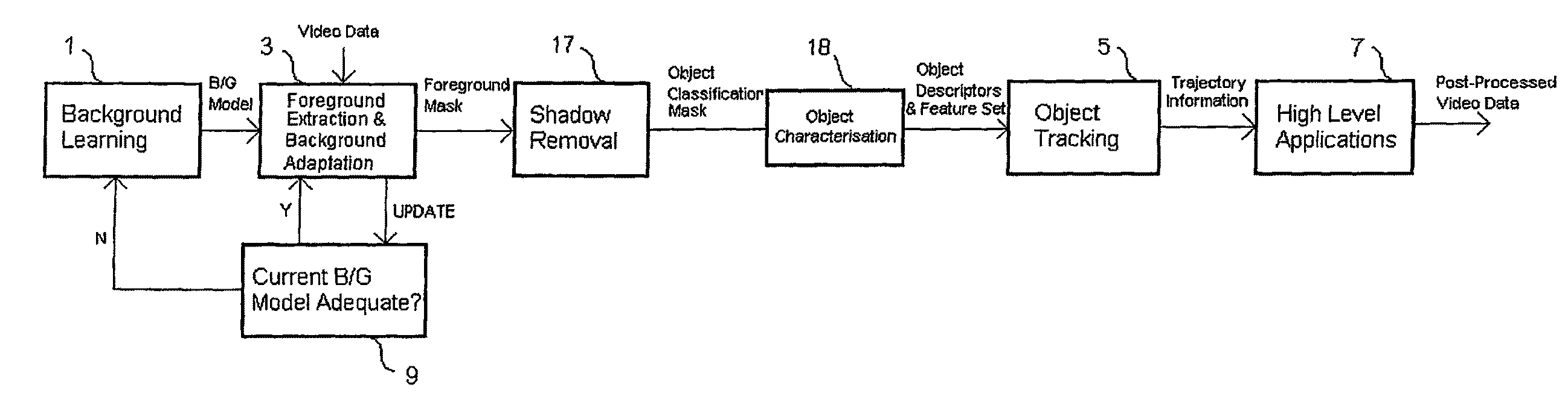
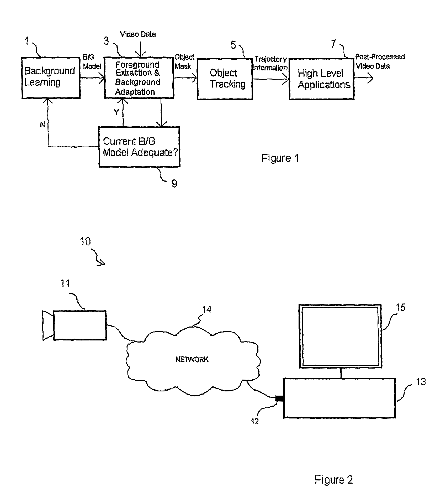
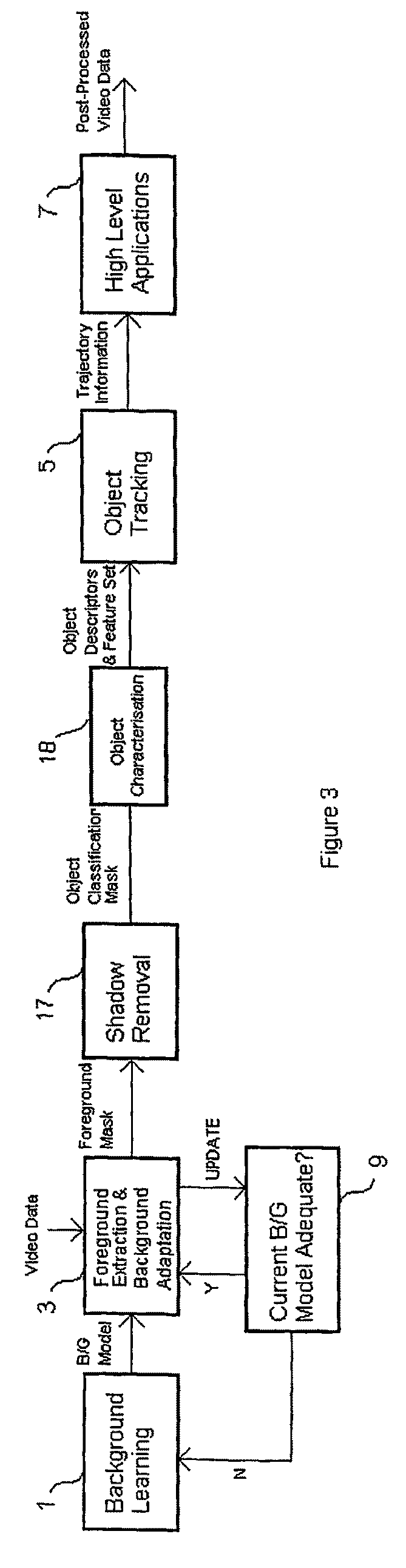
[0011]According to a first aspect of the invention, there is provided a method of tracking an object appearing in a video sequence comprising a plurality of frames, each frame comprising a plurality of pixels, the method comprising: (i) comparing first and second frames of the video sequence to identify a region of pixels therein representing an object having inter-frame motion; (ii) determining whether said region appears in a predetermined number of subsequent frames, and, if so, assigning a motion parameter to said region indicative of the change in position thereof over said predetermined number of frames; (iii) comparing said motion parameter with a threshold value to determine whether or not said region is to be tracked; and (iv) if the region is to be tracked, recording the frame position of said region for subsequent frames in which said region is identified.

[0012]Preferred features of the invention are defined in the dependent claims appended hereto. According to a further ...


PUM


Abstract

In a digital video surveillance system, a number of processing stages are employed to identify foreground regions representing moving objects in a video sequence. An object tracking stage 5 is also provided in order to identify a correspondence between candidate objects in a current frame and those that have already been identified in one or more previous frames. In this way, it is possible to calculate the path taken by the or each foreground object and to record this path information in a trajectory database. In order to improve tracking performance, the object tracking stage 5 employs a state transitional object management scheme which determines whether or not a particular object is to be tracked. As part of the object management scheme, spurious objects, which are identified on the basis of their motion characteristics, are deleted from the system. This ensures that valuable processing resources are not wasted tracking unwanted artifacts which may represent, for example, noise or random motion.

Description

CROSS REFERENCE TO RELATED APPLICATIONS[0001]This application is the US national phase of international application PCT / GB2006 / 000393 filed 6 Feb. 2006 which designated the U.S. and claims benefit of GB 0502371.8, dated 4 Feb. 2005, the entire content of which is hereby incorporated by reference.BACKGROUND[0002]1. Field[0003]This invention relates to a method and system for identifying spurious regions in a video frame, particularly a video frame comprising part of a video sequence.[0004]2. Description of Related Art[0005]Digital video processing is used in a wide range of applications. For example, modern video surveillance systems employ digital processing techniques to provide information concerning moving objects in the video. Such a system will typically comprise a video camera connected to a computer system via a direct or network link. The computer system runs software arranged to process and analyse video data supplied from the camera.[0006]FIG. 1 is a block diagram showing ...

Claims


Application Information

Patent Timeline
Patent Type & Authority Patents(United States)
IPC IPC(8): G06K9/00G06T7/20
CPCG06T7/2006G06T7/215
Inventor LEI, BANGJUNXU, LI-QUN
Owner BRITISH TELECOMM PLC
Why Eureka
Try Eureka