Drive control circuit for electric motor

a technology of drive control circuit and electric motor, which is applied in the direction of motor/generator/converter stopper, electronic commutator, dynamo-electric converter control, etc., can solve problems such as the association of change of excitation interval, and achieve the effect of saving power

Inactive Publication Date: 2011-10-25
GK BRIDGE 1
View PDF17 Cites 24 Cited by
  • Summary
  • Abstract
  • Description
  • Claims
  • Application Information

AI Technical Summary

Benefits of technology

[0009]According to this configuration, since the coil of the electric motor is not provided with a current in the first interval, it is possible to enhance electric power saving of the electric motor.
[0011]According to this configuration, the excitation interval of the drive signal of the electric motor may be formed at will using a digital circuit. By establishing the excitation interval in this way, it is possible to accomplish angle advance control and angle delay control of the electric motor as well.

Problems solved by technology

A resultant problem is that in the event that the resistance value changes owing to temperature changes for example, there is an associated change of excitation interval as well.

Method used


Image

  • Drive control circuit for electric motor
  • Drive control circuit for electric motor
  • Drive control circuit for electric motor

Examples


embodiment 1

A. Embodiment 1

[0060]A1. Overview of Motor Configuration and Operation:

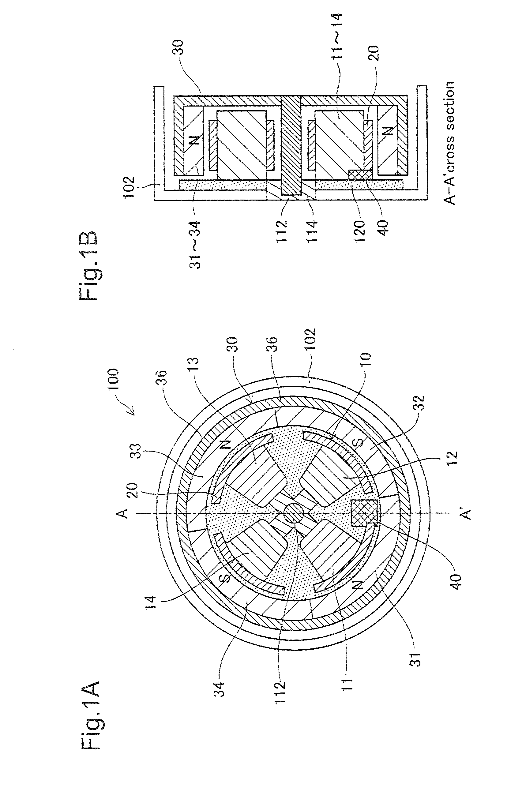
[0061]FIGS. 1A and 1B are sectional views depicting the configuration of the motor unit of a single-phase brushless motor in Embodiment 1. This motor unit 100 has a stator portion 10 and a rotor portion 30, each of generally cylindrical tube shape. The stator portion 10 has four coils 11-14 arranged in a generally cross-shaped pattern, and a magnetic sensor 40 positioned at a center location between two of the coils 11, 12. The magnetic sensor 40 is used to detect the position of the rotor portion 30 (i.e. the phase of the motor). Each coil 11-14 is provided with a magnetic yoke 20 formed of a magnetic material. The coils 11-14 and the magnetic sensor 40 are affixed on a circuit board 120 (FIG. 1B). The circuit board 120 is affixed to a casing 102. The cover of the casing 102 is omitted in the drawing.

[0062]The rotor portion 30 has four permanent magnets 31-34; the center axis of the rotor portion 30 constitutes ...

embodiment 2

B. Embodiment 2

[0110]FIG. 19 is an illustration depicting the configuration of an excitation interval signal generator 590b in embodiment 2. The only differences from Embodiment 1 shown in FIG. 16 are that the second counter 596 is omitted; the first counter 594b has different operation; and there is additional latch timing for the counter value storage 598 and the two arithmetic operation result storages 608, 610; the configuration is otherwise identical to Embodiment 1. The operation of these elements is described below.

[0111]FIG. 20 is a timing chart depicting operation of the excitation interval signal generator 590b in Embodiment 2. On the basis of the clock signal PCL supplied by the controller 592, the first counter 594b counts the number of clock pulses during the interval for which the voltage comparator signal SC shows High level, and the number of clock pulses during the interval for which it shows Low level. Specifically, the first counter 594b starts the count at the ti...

embodiment 3

C. Embodiment 3

[0115]FIG. 21 is an illustration depicting the configuration of an excitation interval signal generator 590c in embodiment 3. The only differences from Embodiment 1 shown in FIG. 16 are that a selector 620 is added; and the second counter 596 is omitted; the configuration is otherwise identical to Embodiment 1. At motor startup, the selector 620 outputs the excitation interval signal Ea which indicates High level constantly. Then, at the point in time that the motor has reached a prescribed rotation speed or a point in time after a prescribed time has passed, the selector 620 switches signals and outputs a signal by the comparator circuit 612 as the excitation interval signal Ea. The timing of this switch is set in the selector 620 in advance by the CPU 220. The operation of these elements is described below.

[0116]FIG. 22 is a timing chart depicting operation of the excitation interval signal generator 590c in Embodiment 3. The only differences from Embodiment 1 shown...


PUM


Abstract

The drive control circuit for an electric motor is provided. The drive control circuit includes: an original drive signal generator that generates an original drive signal; an excitation interval setter that is able, for each half cycle of respective length π in each 2π excitation cycle of the original drive signal, to arbitrarily set excitation intervals during which to excite coils of the electric motor to any one of a plurality of intervals which include at least either one of a symmetrical interval centered on a center of each half-cycle and an unsymmetrical interval; and a drive signal shaping circuit that generates a drive signal for driving the electric motor, by validating the original drive signal during the excitation intervals and invalidating the original drive signal during non-excitation intervals other than the excitation interval.

Description

CROSS-REFERENCE TO RELATED APPLICATIONS[0001]The present application claims the priority based on Japanese Patent Applications No. 2007-175469 filed on Jul. 3, 2007; No. 2007-340803 filed on Dec. 28, 2007; and No. 2008-127574 filed on May 14, 2008, the disclosures of which are hereby incorporated by reference in their entireties.BACKGROUND OF THE INVENTION[0002]1. Field of the Invention[0003]The present invention relates to control of excitation interval of the coils of an electric motor.[0004]2. Description of the Related Art[0005]In a electric motor disclosed in WO2005 / 112230 A1, a drive signal of the electric motor is masked to reduce power consumption.[0006]With this technology, the excitation interval of the drive signal is specified using an analog circuit which employs resistance. A resultant problem is that in the event that the resistance value changes owing to temperature changes for example, there is an associated change of excitation interval as well. Also, there has bee...

Claims


Application Information

Patent Timeline
Patent Type & Authority Patents(United States)
IPC IPC(8): H02P6/08H02K21/22
CPCH02P6/008H02P6/16H03K7/08H02P6/26H02P1/16H02P1/00
Inventor TAKEUCHI, KESATOSHISEJIMO, ISAMUSUZUKI, TAKAFUMI
Owner GK BRIDGE 1
Why Eureka
Try Eureka