Drive control circuit for electric motor
- Summary
- Abstract
- Description
- Claims
- Application Information
AI Technical Summary
Benefits of technology
Problems solved by technology
Method used
Image
Examples
embodiment 1
A.
[0068]A1. Overview of Motor Configuration and Operation:
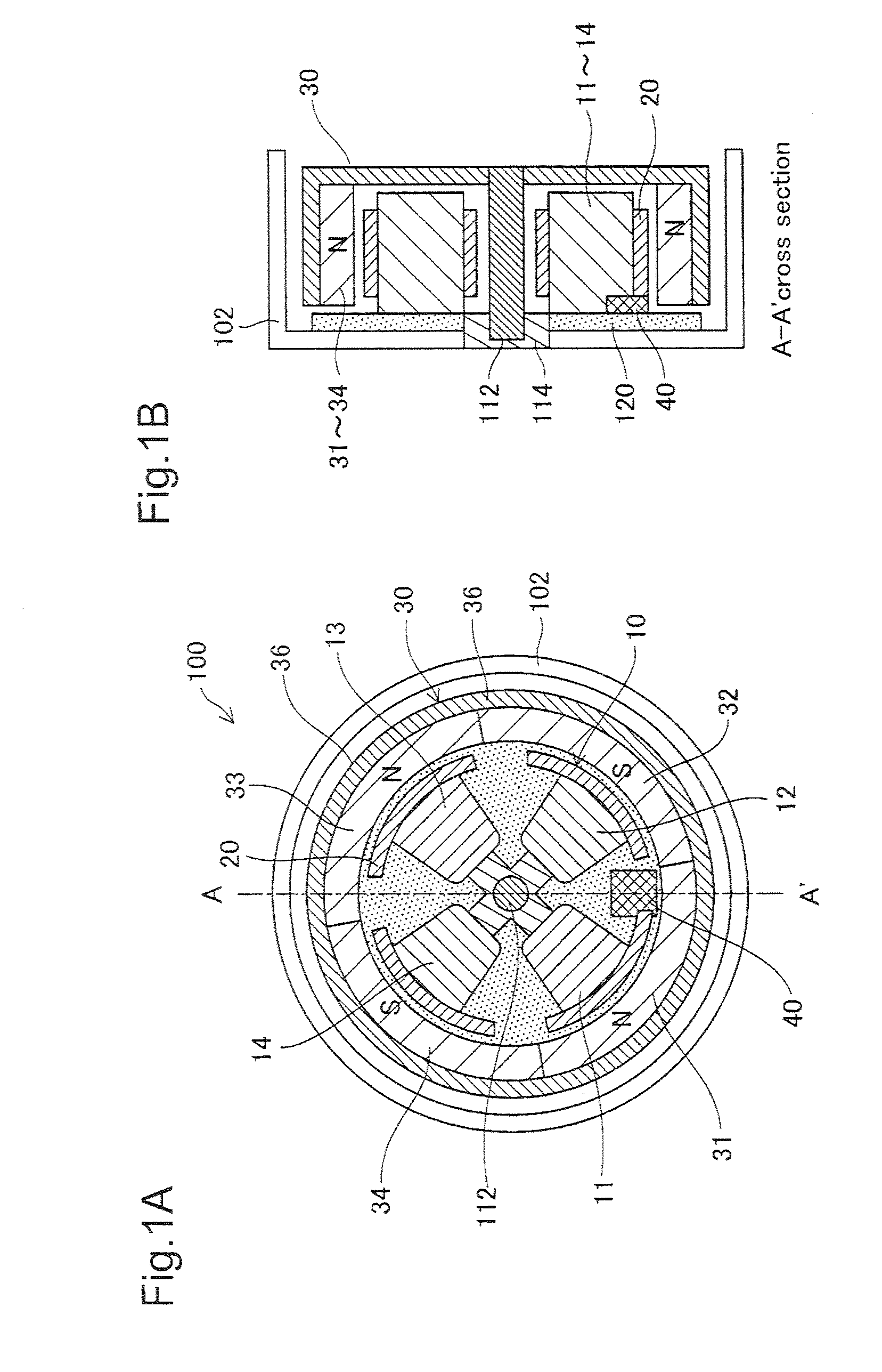
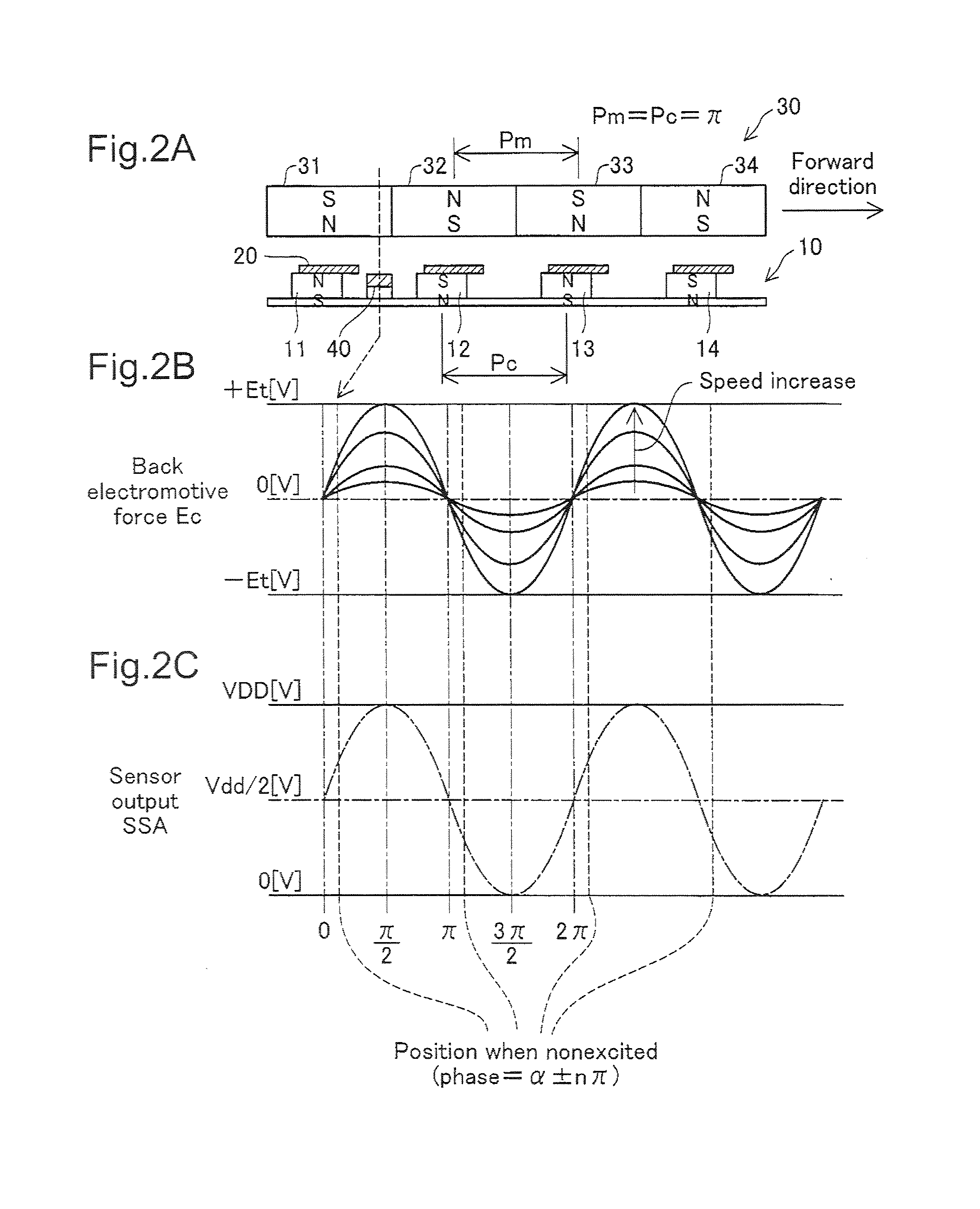
[0069]FIGS. 1A and 1B are sectional views depicting the configuration of the motor unit of a single-phase brushless motor in Embodiment 1. This motor unit 100 has a stator portion 10 and a rotor portion 30, each of generally cylindrical tube shape. The stator portion 10 has four coils 11-14 arranged in a generally cross-shaped pattern, and a magnetic sensor 40 positioned at a center location between two of the coils 11, 12. The magnetic sensor 40 is used to detect the position of the rotor portion 30 (i.e. the phase of the motor). Each coil 11-14 is provided with a magnetic yoke 20 formed of a magnetic material. The coils 11-14 and the magnetic sensor 40 are affixed on a circuit board 120 (FIG. 1B). The circuit board 120 is affixed to a casing 102. The cover of the casing 102 is omitted in the drawing.
[0070]The rotor portion 30 has four permanent magnets 31-34; the center axis of the rotor portion 30 constitutes a rotating sh...
embodiment 2
B.
[0118]FIG. 19 is an illustration depicting the configuration of an excitation interval signal generator 590b in embodiment 2. The only differences from Embodiment 1 shown in FIG. 16 are that the second counter 596 is omitted; the first counter 594b has different operation; and there is additional latch timing for the counter value storage 598 and the two arithmetic operation result storages 608, 610; the configuration is otherwise identical to Embodiment 1. The operation of these elements is described below.
[0119]FIG. 20 is a timing chart depicting operation of the excitation interval signal generator 590b in Embodiment 2. On the basis of the clock signal PCL supplied by the controller 592, the first counter 594b counts the number of clock pulses during the interval for which the voltage comparator signal SC shows High level, and the number of clock pulses during the interval for which it shows Low level. Specifically, the first counter 594b starts the count at the timing at which...
embodiment 3
C.
[0123]FIG. 21 is an illustration depicting the configuration of an excitation interval signal generator 590c in embodiment 3. The only differences from Embodiment 1 shown in FIG. 16 are that a selector 620 is added; and the second counter 596 is omitted; the configuration is otherwise identical to Embodiment 1. At motor startup, the selector 620 outputs the excitation interval signal Ea which indicates High level constantly. Then, at the point in time that the motor has reached a prescribed rotation speed or a point in time after a prescribed time has passed, the selector 620 switches signals and outputs a signal by the comparator circuit 612 as the excitation interval signal Ea. The timing of this switch is set in the selector 620 in advance by the CPU 220. The operation of these elements is described below.
[0124]FIG. 22 is a timing chart depicting operation of the excitation interval signal generator 590c in Embodiment 3. The only differences from Embodiment 1 shown in FIG. 17 a...
PUM
 Abstract
Description
Claims
Application Information
 - R&D
- Intellectual Property
- Life Sciences
- Materials
- Tech Scout
- Unparalleled Data Quality
- Higher Quality Content
- 60% Fewer Hallucinations
Browse by: Latest US Patents, China's latest patents, Technical Efficacy Thesaurus, Application Domain, Technology Topic, Popular Technical Reports.
© 2025 PatSnap. All rights reserved.Legal|Privacy policy|Modern Slavery Act Transparency Statement|Sitemap|About US| Contact US: help@patsnap.com


