Solid insulated bus switchgear

a switchgear and solid-insulated technology, applied in the field of switchgear, can solve problems such as circuit breakers, and achieve the effect of greatly reducing the number of cabinets

Inactive Publication Date: 2011-10-25
HITACHI LTD
View PDF11 Cites 15 Cited by
  • Summary
  • Abstract
  • Description
  • Claims
  • Application Information

AI Technical Summary

Benefits of technology

[0008]In the electric power reception and distribution switchgear described above, an abnormality such as an earth fault caused in the system is detected by the current transformer disposed near the load of the circuit breaker and by the zero-phase sequence current transformer disposed near the power supply of the circuit breaker, and thereby the circuit breaker trips. Accordingly, the entire load including the circuit breaker can be protected from an earth fault and the range of protection can be expanded, improving the reliability in protection against earth faults. Since the main buses are solid-insulated, maintenance to prevent short-circuits, which otherwise would be caused by dust buildups, is eliminated, saving in maintenance labor. Furthermore, since the solid-isolated main buses and the like are placed in the main bus room behind the unit rooms to shorten the insulation distances among the main buses, the storage space is reduced, enabling the entire apparatus to be downsized.
[0020]According to the present invention, a circuit breaker and an instrument voltage transformer are placed in a single switching unit, so a parallel circuit between the circuit breaker and instrument voltage transformer can be formed with a single stage. By comparison, this type of parallel circuit requires two stages in the stacking structure of a conventional switchgear for electric power reception and distribution. Accordingly, in a side-by-side configuration, the number of cabinets can be greatly reduced, and thereby an area in which switchgears for electric power reception and distribution can be greatly reduced when they are installed side by side.

Problems solved by technology

In the electric power reception and distribution switchgear described above, an abnormality such as an earth fault caused in the system is detected by the current transformer disposed near the load of the circuit breaker and by the zero-phase sequence current transformer disposed near the power supply of the circuit breaker, and thereby the circuit breaker trips.

Method used


Image

  • Solid insulated bus switchgear
  • Solid insulated bus switchgear
  • Solid insulated bus switchgear

Examples


first embodiment

[0031]A first embodiment of a solid insulated bus switchgear in the present invention will be described below with reference to the drawings.

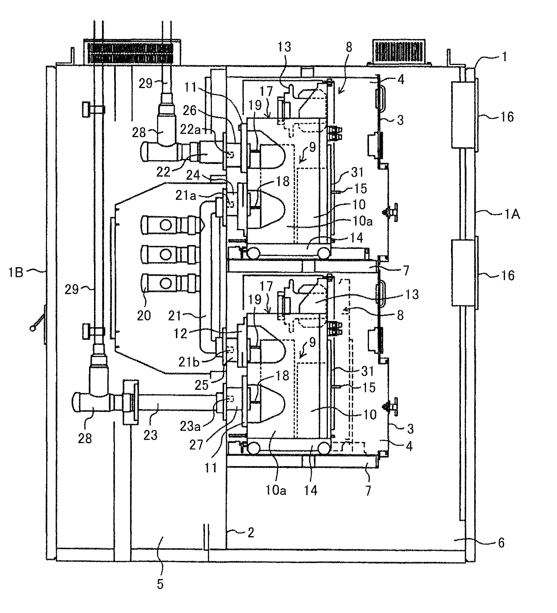
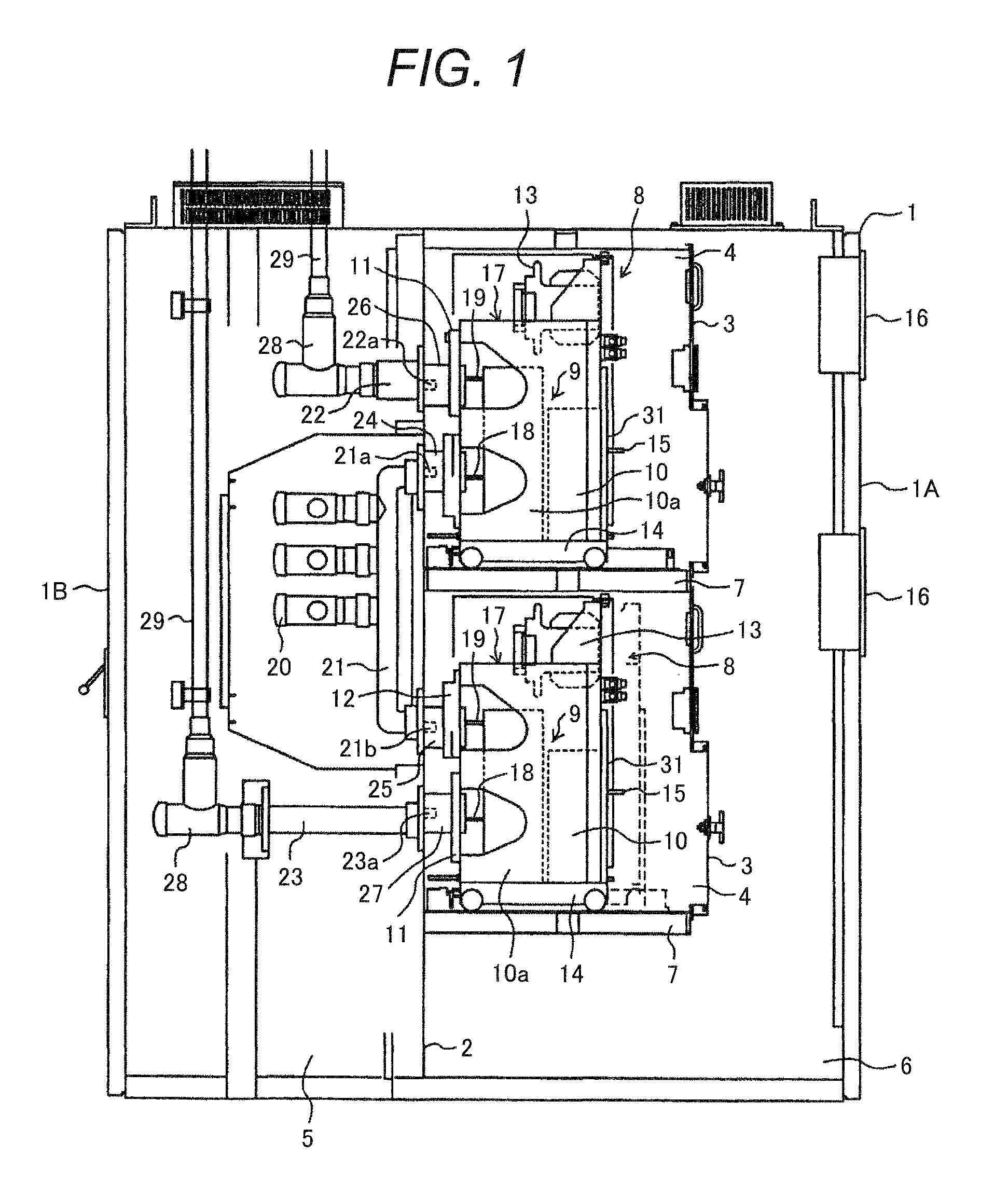
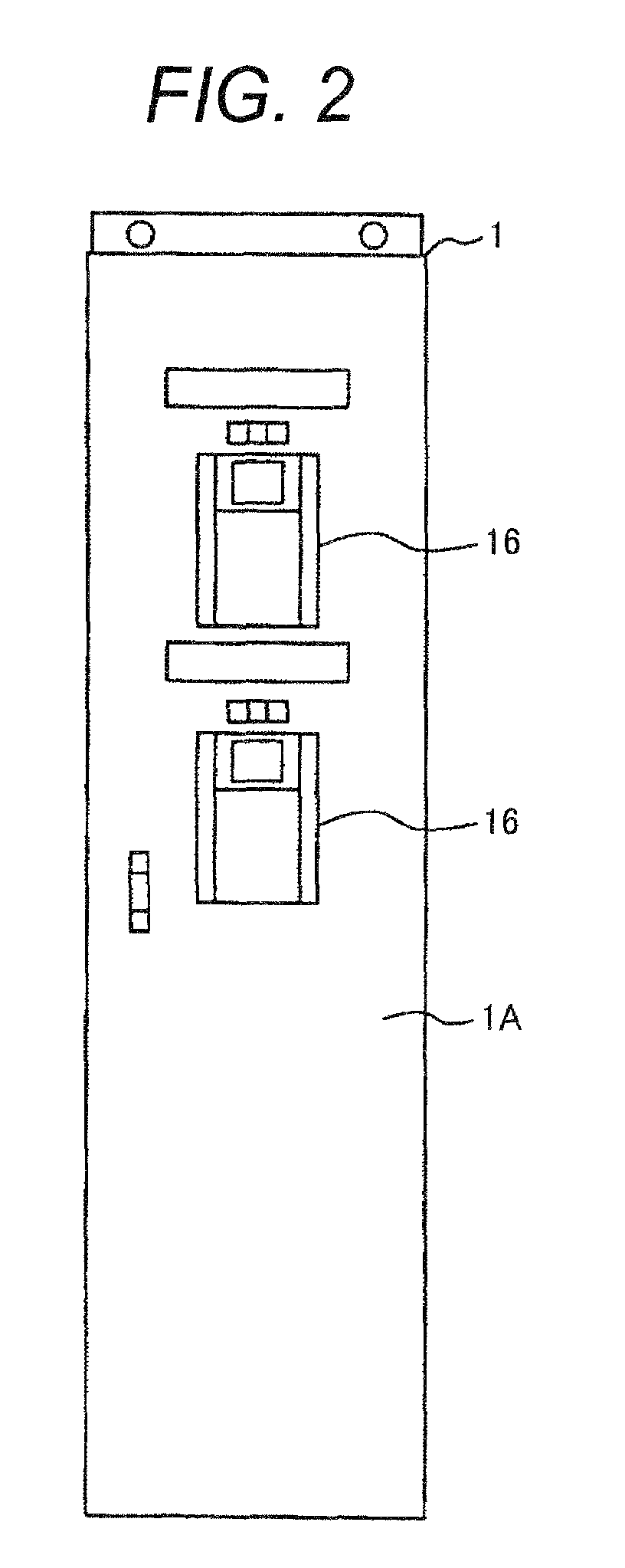
[0032]FIGS. 1 to 3 show a solid insulated bus switchgear in a first embodiment of the present invention; FIG. 1 is a vertical cross sectional view of the solid insulated bus switchgear, FIG. 2 is a front view of the solid insulated bus switchgear in FIG. 1, and FIG. 3 is a schematic connection diagram of the solid insulated bus switchgear in FIG. 1.

[0033]In FIGS. 1 to 3, the cabinet 1 of the solid insulated bus switchgear is partitioned by a partitioning plate 2, which is a ground metal plate, into a front side and a rear side. A bus room 5 is defined on the rear side (left side in FIG. 1), and two unit rooms 4 are vertically defined with sealed covers 3 in a control room 6 on the front side (right side in FIG. 1). A front door 1A, which is openable and closable, is provided on the front of the cabinet 1, and rear door 1B, which is also openabl...

second embodiment

[0062]A solid insulated bus switchgear in the second embodiment of the present invention is structured with a circuit equivalent to an ordinary electric power reception and distribution switchgear of this type. The solid insulated bus switchgear in this embodiment differs from the solid insulated bus switchgear in the first embodiment in the following points; other points are the same as in the first embodiment.

[0063](1) In the solid insulated bus switchgear in the second embodiment of the present invention, three unit rooms 4 are vertically stacked, each of which is defined by a partitioning plate 2 and a sealing cover 3, as shown in FIG. 7. Accordingly, a total of three switching units 8 are needed, one switching unit in one unit room 4. FIG. 9 shows the structure of the three switching units 8; the switching unit 8 in the upper stage includes a vacuum circuit breaker 9, a disconnecting part 80 disposed near the fixed electrode of the vacuum circuit breaker 9, another disconnectin...


PUM


Abstract

A solid insulated bus switchgear including a cabinet having unit and bus rooms, first and second switching units, each having a circuit breaker, current transformer, zero-phase sequence current transformer, and instrument voltage transformer, main buses, a communication bus linked to the main buses, and connected to the first and the second switching units, and first and second leader buses, the first connected to the first switching unit, the second connected to the second switching unit. Each switching unit has a movable cart, the circuit breaker mounted on the cart, and a frame assembly. Two terminals are disposed on the back of the circuit breaker, one connected to a fixed electrode and the other connected to a movable electrode of the circuit breaker. The two terminals are connected to the communication bus and to the first or second leader bus through air bushings.

Description

CLAIM OF PRIORITY[0001]The present application claims priority from Japanese patent application serial No. 2008-176665, filed on Jul. 7, 2008, the content of which is hereby incorporated by reference into this application.BACKGROUND OF THE INVENTION[0002]1. Field of Technology[0003]The present invention relates to a switchgear in an electric power reception and distribution facility, and more particularly to a switchgear that is structured with circuit breakers, current transformers, zero-phase sequence current transformers, instrument voltage transformers, and the like.[0004]2. Background of Art[0005]In general, a switchgear for electric power reception and distribution is structured by placing, in its case, circuit breakers, disconnecting switches, current transformers, zero-phase sequence current transformers, instrument voltage transformers, and the like. The circuit breaker and disconnecting switch are mounted as a unit on a cart that can be drawn. The circuit breaker and disco...

Claims


Application Information

Patent Timeline
Patent Type & Authority Patents(United States)
IPC IPC(8): H02B13/02
CPCH02B13/01H02B11/26H01H71/50H02B11/127H02B13/035H02B15/00
Inventor KUROGI, TAKUYATSUCHIYA, KENJIISHIKAWA, TAKUMINAKATSUGAWA, NAOKI
Owner HITACHI LTD
Why Eureka
Try Eureka