Face plate alignment system

a technology of face plate and alignment system, which is applied in the field of pull-out cabinet slides, pantries and drawers, can solve the problems of affecting the appearance of the drawer, and promoting the likelihood of dust and debris entering the drawer, so as to achieve the effect of less time, less cost, and easy operation

Active Publication Date: 2011-11-01
REV A SHELF
View PDF41 Cites 20 Cited by
  • Summary
  • Abstract
  • Description
  • Claims
  • Application Information

AI Technical Summary

Benefits of technology

[0010]The face plate alignment mounting system of another embodiment of the present invention can further include a threaded fastener that includes a shaft having a first portion with external threads engaging the drawer body through a second bore of the drawer body. The second bore is preferably perpendicular to the drawer front panel. The threaded fastener shaft can also include a second portion extending from the first portion and outward passed the drawer front panel, with the second portion engaging the lateral adjustment means. A head portion can also be provided with the threaded fastener, which can extend from the threaded fastener shaft. The face plate alignment mounting system can also include a second nut fastener that has internal threads for threadably engaging the external threads of the threaded fastener shaft at the rear surface of the drawer front panel. When the second nut fastener is threadably engaged sufficiently tight with the external threads of the threaded fastener shaft, the drawer face plate can be prevented from adjusting in a lateral direction. The face plate alignment mounting system can also include a washer for receiving the threaded fastener shaft and contacting the second nut fastener and the drawer front panel at the rear surface of the drawer front panel. The lateral adjustment means preferably includes a support bracket. The support bracket can include a slot and two parallel edges curved substantially perpendicular. The curved edges can slidably engage with two laterally running, parallel grooves in the drawer front panel for adjusting the face plate in a lateral direction.
[0012]One feature of the present is that the adjustment and alignment of the drawer face panel relative to an adjacent drawer face panel can be performed easily, less expensively, and in less time. The drawer face panel can be easily adjusted in an inward and an outward direction, or a rearward and frontward direction, to compensate for differing degrees of tilt and skew of the drawer face panel with adjacent drawer face panels.

Problems solved by technology

Tilt in the roll direction of a drawer face panel can result when the bottom of the face panel of a closed drawer may be in contact with the enclosure, but the top is not, yielding a gap between the top of the face and the cabinet.
This not only promotes the likelihood of dust and debris entering the drawer through the gap, but also yields a displeasing appearance especially when the adjacent drawer face panels have differing degrees of tilt.
These schemes, however, tend to be expensive due to the number of components involved and the tightness of the tolerances required to yield that favorable alignment.
For example, in the low cost cabinet industry, tolerances are not expected to be held sufficiently tight, yet poor drawer face alignment is in fact more common.
However, most of these schemes are accomplished using the time consuming trial and error method, i.e., an adjustment is made, followed by closing the drawer and checking its position, followed by another adjustment, with this process being repeated until a suitable adjustment has been obtained.

Method used


Image

  • Face plate alignment system
  • Face plate alignment system
  • Face plate alignment system

Examples


Embodiment Construction

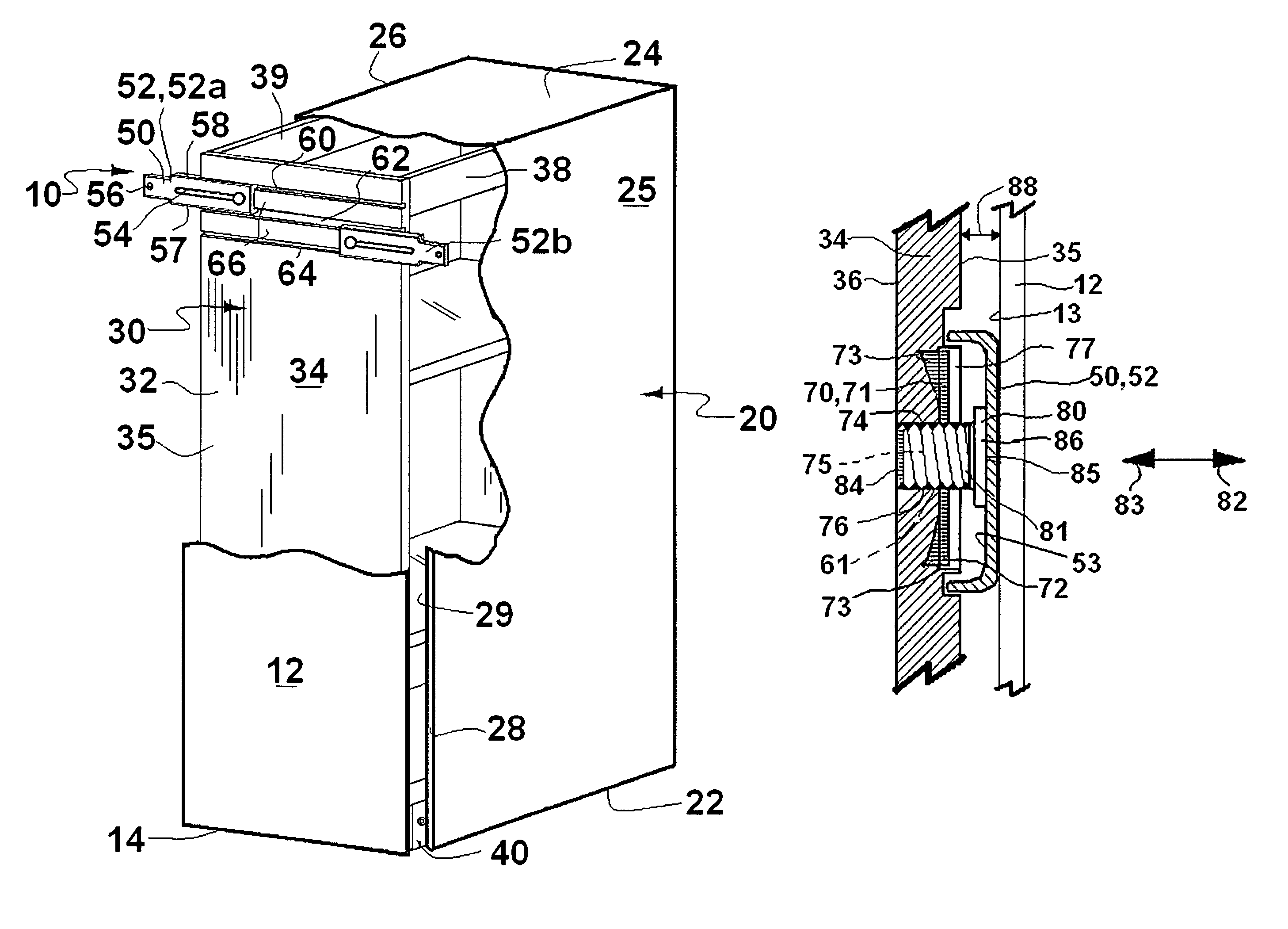
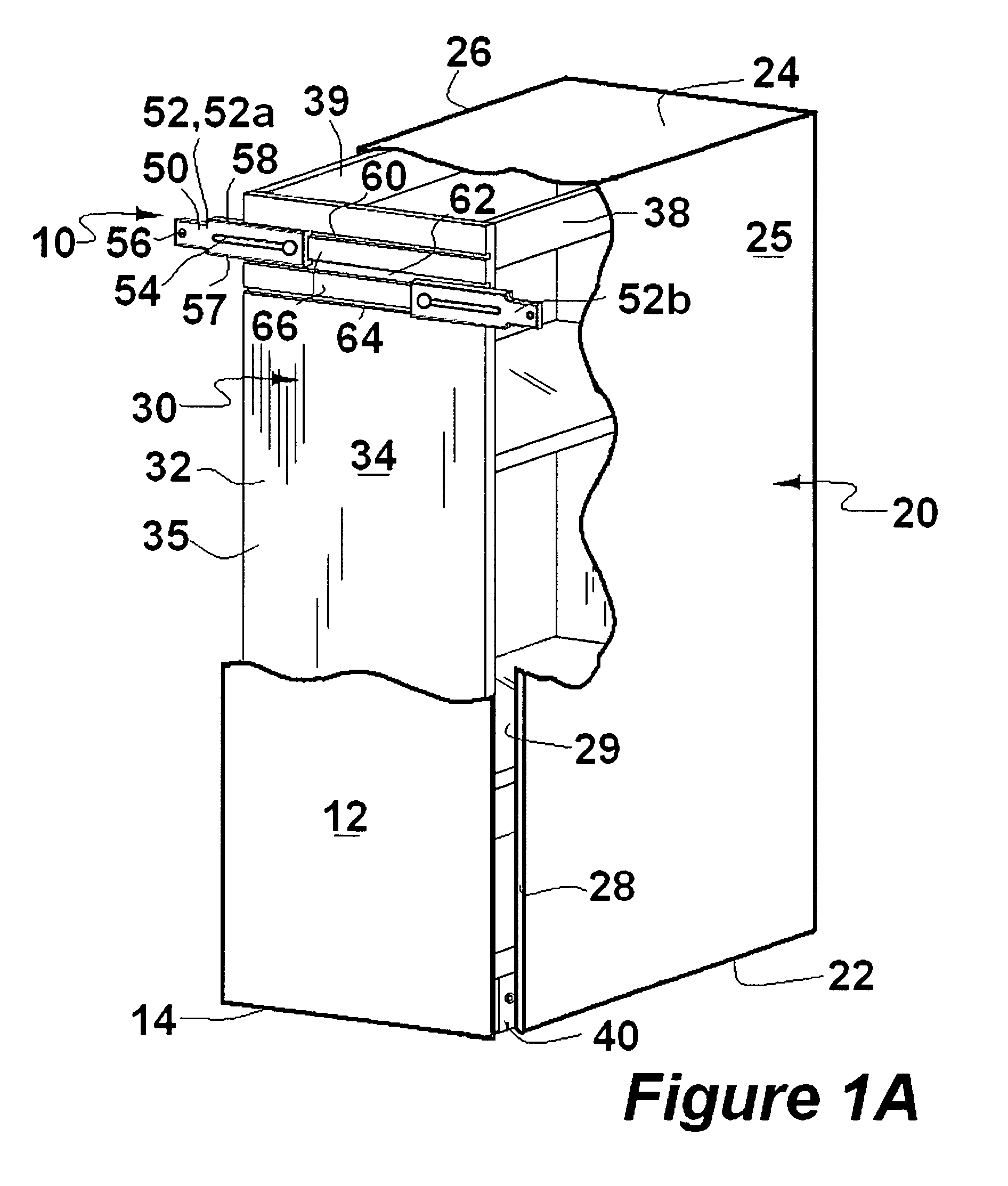
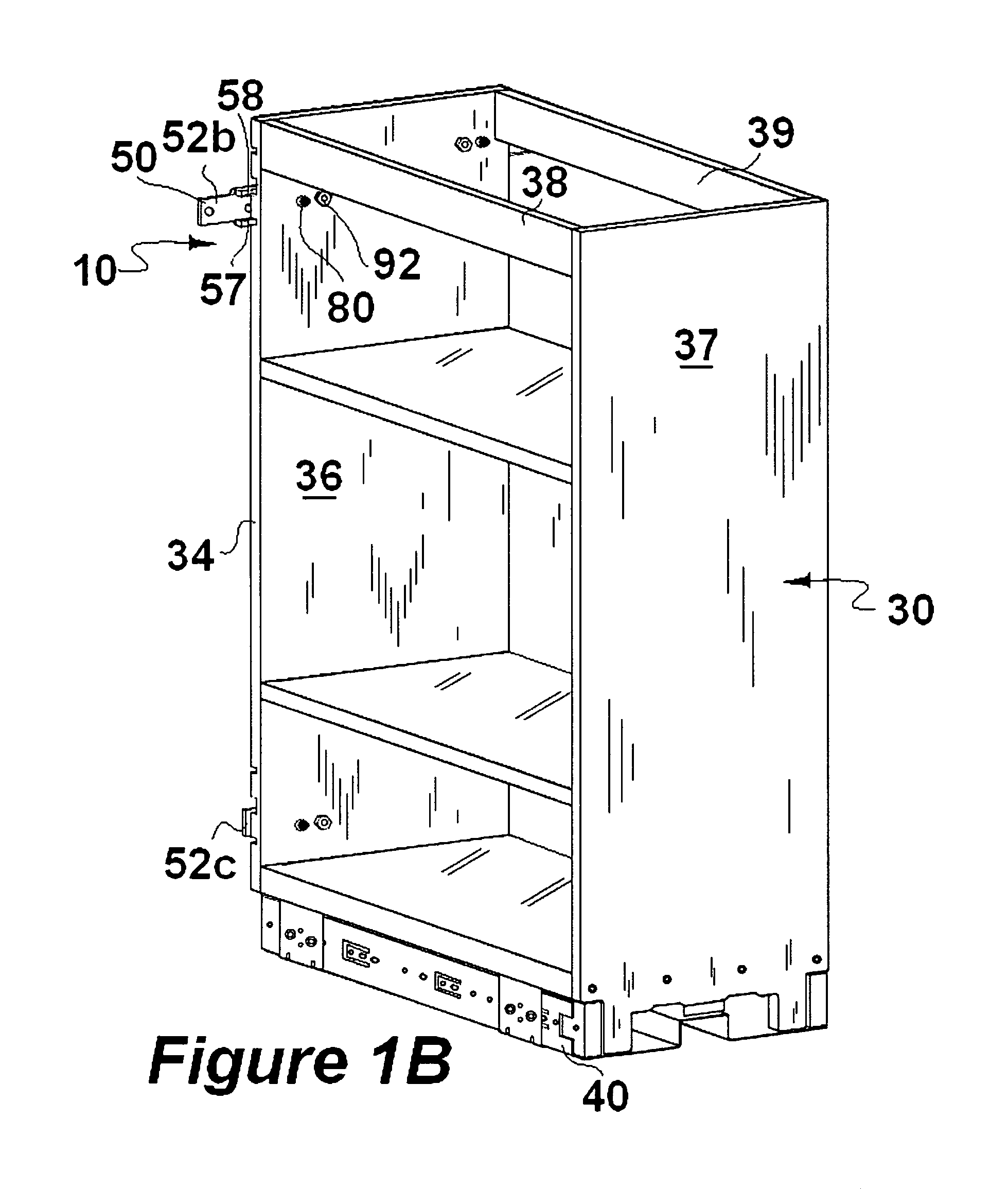
[0020]Referring to FIG. 1A, a face plate alignment mounting system 10 is depicted for adjustably mounting a drawer face plate 12 having an outer portion 14 into a desired position relative to an enclosure 20. FIG. 1B is a perspective rear view of the face plate alignment mounting system 10 attached to a drawer 30, depicted without the drawer face plate 12 and the enclosure 20. While the term “door” is often used in the industry to refer to any panel-like structure having a vertical dimension exceeding the horizontal dimension, in the present document the term “drawer” is used to refer to any structure that is received in a sliding fashion, instead of a pivoting fashion, in a cabinet or other similar structure, regardless of its relative vertical and horizontal dimensions. It is to be understood that the enclosure 20 may be a kitchen or bathroom cabinet, a paper file cabinet, a tool chest, an industrial or consumer storage cabinet, or any of a variety of enclosures used for housing a...


PUM

PropertyMeasurementUnit
distanceaaaaaaaaaa
areaaaaaaaaaaa
perimeteraaaaaaaaaa

Abstract

A system for adjustably mounting the face plate of a drawer so that when the drawer is closed, the drawer face plate is flush with the adjacent drawer face plate and in a desired height, pitch, roll, lateral and skew position with respect to the front surface of the enclosure. The drawer face panel can be easily adjusted in an inward and outward direction, or a rearward and frontward direction, to compensate for differing degrees of tilt and skew of the drawer face panel with adjacent drawer face panels. A face plate alignment mounting system is provided and includes a lateral adjustment mechanism that engages a face plate and a drawer front panel, a first nut fastener, and an adjustable fastener. The first nut fastener preferably includes a head portion that is affixed to a drawer body and a shaft slidably engaged with a first bore of the drawer body. The first nut fastener shaft defines an opening with internal threads. The adjustable fastener has external threads engaged with the internal threads of the first nut fastener shaft opening. The adjustable fastener includes a first mechanism for adjusting the adjustable fastener in a frontward direction and a rearward direction to suitably adjust the distance between the face plate and said drawer front panel, which is preferably accessible at the rear surface of the drawer front panel.

Description

BACKGROUND OF THE INVENTION[0001]1. Field of the Invention[0002]The present invention generally relates to pull-out cabinet slides, pantries and drawers that have face plates or fronts attached to match or otherwise complement the visual appearance of an adjacent cabinetry. The present invention particularly relates to a mounting system that facilitates the alignment of a face plate or drawer front.[0003]2. Description of the Prior Art[0004]Typically, when a drawer is installed into a cabinet, the face panel of the drawer may or may not be aligned with the adjacent cabinet in any or all of three dimensions. For both aesthetic and functional reasons, it is desirable that the face of the drawer be in alignment with the faces of any other drawers or cabinet doors that are also installed into the cabinet or adjacent cabinets. The drawer face panel is typically mounted onto the drawer itself, which is mounted onto a drawer slide, or it may be mounted directly to the drawer slide. In eith...

Claims


Application Information

Patent Timeline
Patent Type & Authority Patents(United States)
IPC IPC(8): A47B88/00
CPCA47B88/0055Y10T29/49963A47B88/956
Inventor WALBURN, WILLIAM L.
Owner REV A SHELF
Why Eureka
Try Eureka