Tube blanket

a tube blanket and tube technology, applied in the field of convective heating blankets, can solve the problem of uneven warming of patients, and achieve the effect of uniform distribution

Active Publication Date: 2011-11-01
SMITHS MEDICAL ASD INC
View PDF16 Cites 1 Cited by
  • Summary
  • Abstract
  • Description
  • Claims
  • Application Information

AI Technical Summary

Benefits of technology

[0004]The inventors have found that by varying the size of the holes incrementally along the legs of the U tube blanket, for example from the proximal portions of the legs that are closest to the air inlet cross section where heated air is input to the blanket to the distal portions of the legs that are furthest away from the cross section, the warm air vented from the differently dimensioned vent holes is more evenly distributed, thereby providing for an evenly distributed layer of warm air for the patient.
[0005]It is further found that if the vent holes along the length of each leg of the tube blanket were to be formed in at least two rows with the respective sizes of the holes incrementally varied along the length of the leg, so that when the blanket is inflated the rows of vent holes from the two legs of the blanket are in substantially opposed alignment with each other for directing the vented warm air to both sides of the patient positioned there between, the heated air output to the patient is more evenly distributed over the patient than prior tube blankets. Moreover, it was found that a more optimal and efficient warming U-tube blanket may be obtained if the vent holes along each leg of the blanket were to be grouped into sections along the length of the legs of the blanket, with the holes in each of the sections having the same dimension.
[0009]The present invention also relates to a U-shaped tube blanket that comprises an air input cross section for receiving heated air from a convective warmer; two legs each extending from a corresponding end of the cross section, wherein said each leg includes holes extending substantially along the length thereof wherethrough the heated air vents, the holes having sizes that incrementally increase from a proximal portion adjacent the cross section to a distal section away from the cross section so that the amount of heated air output from the distal portion is greater than the amount of heated air output from the proximal portion of the legs to thereby provide substantially evenly distributed warmth from the heated air for a patient placed between the two legs.

Problems solved by technology

Thus, uneven warming of the patient results.

Method used


Image

  • Tube blanket
  • Tube blanket

Examples


Embodiment Construction

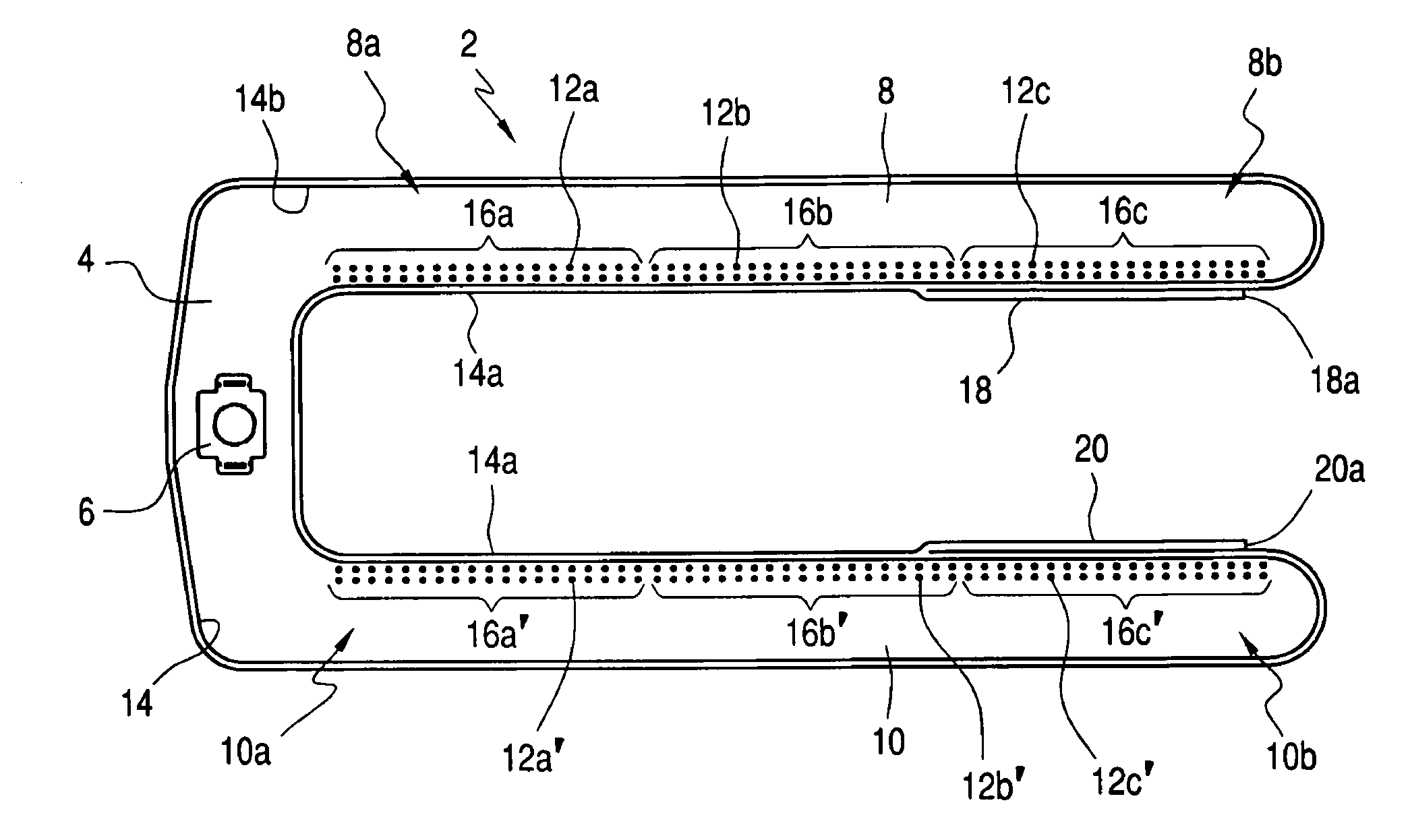
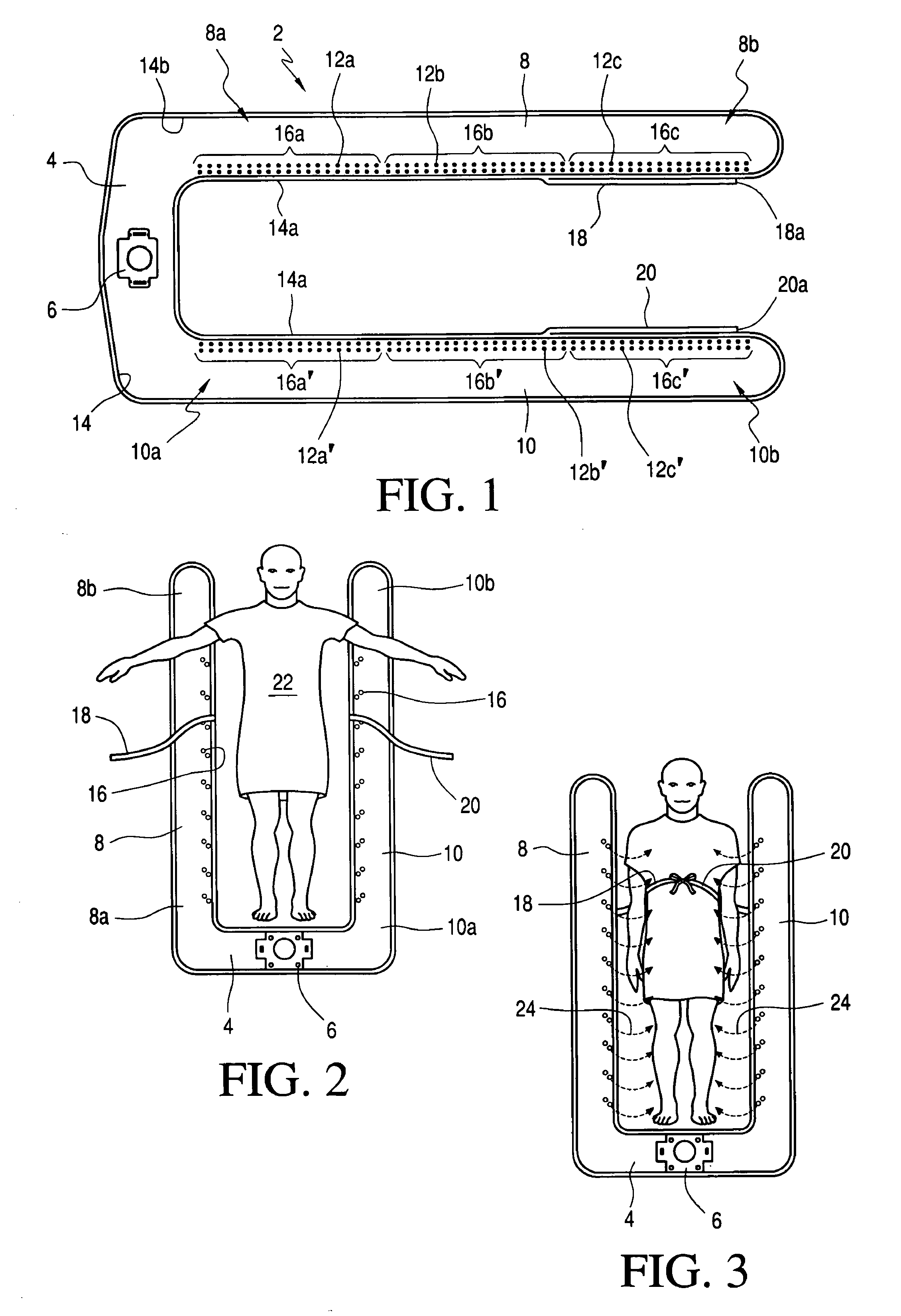
[0015]With reference to FIG. 1, a U tube blanket 2 is shown to have an air inlet cross section 4 having an inlet orifice 6 into which heated air from a convective warmer (not shown) is input by means of a hose, as is commonly known. The input orifice 6 for the U tube blanket 2 may be configured with the type of input that is described in co-pending application Ser. No. 11 / 401,957, assigned to the same assignee as the instant invention. The disclosure of the '957 application is incorporated herein by reference.

[0016]Extending from each end of the cross section 4 is a leg 8, 10. Each of legs 8 and 10 in actuality is a continuation of the cross section 4, as the blanket is made from two layers of air impermeable materials that are bonded at their respective edges so that a continuous rim or flange 14 is formed around the blanket. When thus bonded, the blanket is inflatable when filled with fluid, which for a convective blanket is most likely heated air. In the case where one or more ai...


PUM


Abstract

Each leg of a U tube blanket is configured to have at least one row of holes extending substantially along the length thereof. The size of the holes is incrementally increased from the proximal portion that is closest to the air inlet cross section of the blanket where heated air is input to the blanket for inflating the same to the distal portion of the legs of the blanket. For an embodiment of the inventive blanket, the plurality of vent holes along each leg of the blanket are grouped into a number of sections, for illustration purposes three, with the vent holes in each section having the same dimension. With the size of the holes being incrementally larger along the leg away from the heat source, a greater amount of warm air is output at the distal portion of the blanket to compensate for the distance the warm air needs to travel before it is vented from the blanket. As a result, a substantially evenly distributed bath of warm air is output from the legs of the blanket to the sides of the patient so that the patient is evenly warmed along his entire body. Straps that are separable from the legs of the blanket are provided to secure the blanket to the patient.

Description

FIELD OF THE INVENTION[0001]The present invention relates to convective warming blankets and more specifically to a U-shaped tube blanket that is adapted to be placed around a patient.BACKGROUND OF THE INVENTION[0002]Prior to the instant invention, tube blankets, which may be in the shape of U tubes, are formed with vent holes that have the same dimension. Accordingly, the warm air that outputs from the portions of the U tube blanket that are remote from the air input source tends to be colder than the warm air that outputs from the portions of the blanket close to where the heated air from a convective warmer is input. Thus, uneven warming of the patient results.[0003]There is therefore a need for a U-shaped type convective warming blanket that can bathe a patient with an evenly distributed envelope of warm air.SUMMARY OF THE PRESENT INVENTION[0004]The inventors have found that by varying the size of the holes incrementally along the legs of the U tube blanket, for example from the...

Claims


Application Information

Patent Timeline
Patent Type & Authority Patents(United States)
IPC IPC(8): A61F7/00
CPCA61F7/0097A61F7/02A61F2007/0001A61F2007/0059A61F2007/0091
Inventor PIERRE, JOSEPHSTARR, RACHEL
Owner SMITHS MEDICAL ASD INC
Why Eureka
Try Eureka