
Pyloric valve obstructing devices and methods

a technology of obstructing devices and pyloric valves, applied in the field of medical devices and methods, can solve the problems of obstructing devices dissolving, patient to feel full sooner and longer, etc., and achieve the effects of treating or ameliorating obesity, reducing food intake and weight loss

Active Publication Date: 2011-11-01
BARONOVA
View PDF118 Cites 81 Cited by
  • Summary
  • Abstract
  • Description
  • Claims
  • Application Information

AI Technical Summary

Benefits of technology

[0012]The present invention provides devices, methods and systems for obstructing a pyloric valve to provide weight loss and in some cases treat or ameliorate obesity. Devices are generally delivered into the stomach where they expand or are expanded to partially and / or intermittently obstruct the pyloric valve. By partially or intermittently obstructing the pyloric valve, contents of the stomach (i.e., food) are retained longer in the stomach, thus causing a patient to feel full sooner and longer, and thus leading to reduced food intake and weight loss.
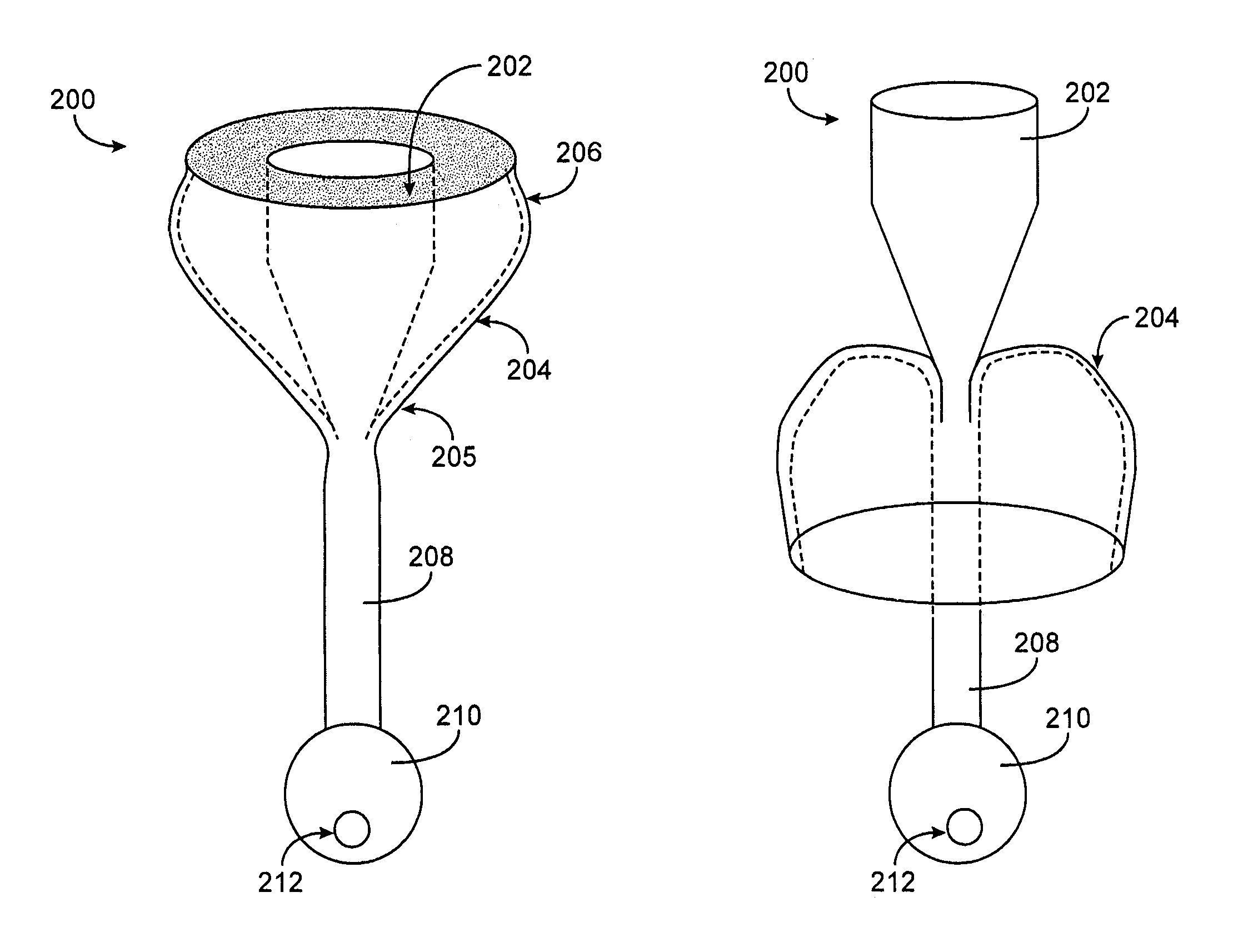
[0014]In one aspect of the present invention, a device for obstructing a pyloric valve of a stomach includes an expandable support portion adapted to expand in the stomach from a first configuration to a larger second configuration, and a compliant tissue engagement portion coupled with the expandable support portion and adapted to engage stomach tissue adjacent the pyloric valve to at least intermittently obstruct the pyloric valve. In the second configuration, the support portion prevents passage of the device through the pyloric valve. In general, the support portion and the tissue engagement portion may have any of a number of different configurations. In one embodiment, the two portions are part of one, unitary extrusion, with the support portion having a greater wall thickness than the tissue engagement portion and / or containing one or more support members, such as support rings, lattices, frames or the like. In other embodiments, the two portions may be separate pieces coupled together. The compliant tissue engagement portion generally is sufficiently compliant so as to prevent or avoid injury (such as erosion) of stomach tissue with which the device comes in contact.
[0016]In alternative embodiments, the self-expanding material may include a self-expanding foam disposed within the expandable support portion and possibly the tissue engagement portion as well. For example, the foam may comprise polyethylene foam, polyurethane foam, silicone foam or the like. Like the support members just described, the expandable foam helps prevent passage of the device through the pyloric valve. Optionally, in some embodiments, the self-expanding material expands upon contacting one or more substances naturally present in the stomach.
[0017]In some embodiments, the support portion and the tissue engagement portion comprise at least one of Gore-tex®, silicone, polyeurethane and polyethylene, with the wall thickness of the support portion being greater than the wall thickness of the tissue engagement portion. In such a device the support portion may also include one or more support members, such as Nitinol rings or the like. In some embodiments, the tissue engagement portion is adapted to temporarily form a seal with the pyloric valve upon contacting the tissue adjacent the valve, and the tissue engagement portion is sufficiently compliant to avoid causing damage to the tissue on contacting it.
[0018]In various embodiments, the obstruction device may have any suitable dimensions, configurations or the like. In one embodiment, for example, the support portion in the second configuration has a widest cross-sectional diameter of between 2.5 cm and 15 cm. The support portion and tissue engagement portion, in one embodiment, have a combined volume in the second configuration greater than 200 cc. This combined volume, in some embodiments, is sufficient to allow the device to act as a space occupying device (as well as a pyloric valve obstructing device) for treating obesity. In addition to its dimensions, the specific gravity or buoyancy of the device may enhance its ability to contact and obstruct the pyloric valve. In one embodiment, for example, the device has a specific gravity of between 0.25 and 4.0. Some embodiments may include one or more chambers for introducing a gas or fluid to adjust the buoyancy of the device, or other mechanisms for adjusting buoyancy.
[0023]A retaining member and / or a positioning member having certain dimensions may be advantageous in various embodiments. For example, in one embodiment a retaining member has a cross-sectional diameter of between 0.5 cm and 3.0 cm. In some embodiments, the positioning member has a length of at least 3.0 cm. In some embodiments, the positioning member has a cross-sectional diameter of 2 cm or less. The positioning member may have a general shape adapted to permit the device to intermittently move into and out of contact with the pyloric valve, such as a cylindrical shape or the like. In some embodiments, the positioning member is adapted to self-expand from a first diameter to a larger second diameter within the pyloric valve. In some embodiments, a distal end of the positioning member is weighted.

Problems solved by technology

By partially or intermittently obstructing the pyloric valve, contents of the stomach (i.e., food) are retained longer in the stomach, thus causing a patient to feel full sooner and longer, and thus leading to reduced food intake and weight loss.
In other embodiments the obstructing device may dissolve over time and pass harmlessly through the digestive tract.

Method used


Image

  • Pyloric valve obstructing devices and methods
  • Pyloric valve obstructing devices and methods
  • Pyloric valve obstructing devices and methods

Examples


Embodiment Construction

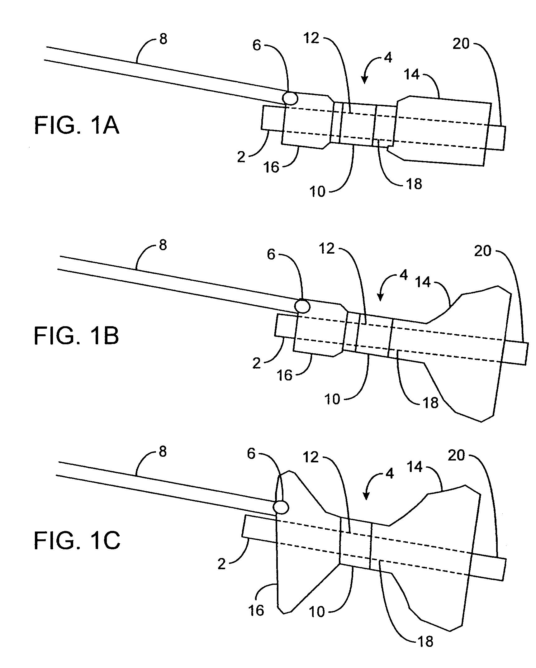
[0063]FIGS. 1A to 1C are cross-sectional views showing the expansion, respectively, of one variation of a pyloric corking device which is designed to partially and / or intermittently obstruct a gastric opening, particularly the pyloric valve. In this particular variation, FIG. 1A illustrates the device 4 in an unexpanded or uninflated state and ready for delivery and / or insertion into the pyloric valve. FIG. 1B shows the distal occlusion member 14 in an expanded state. In use, once the device 4 has been placed, e.g., in the pyloric region or beyond, the distal occlusion member 14 (or “retaining member”) may be inflated through the influx of any number of biocompatible fluids or gases, e.g., saline, water, air, nitrogen, etc., through the tubing 8 leading to the inflation port 6, which may be self-sealing. Tubing 8 may include any number of delivery tubes such as catheters, endoscopes, etc.

[0064]The distal occlusion member 14 may be configured to inflate before the inflation of proxim...


PUM


Abstract

Methods, devices and systems facilitate intermittent and / or partial obstruction of a pyloric valve. Devices generally include a support portion for preventing the device from passing through the pyloric valve and a tissue engagement portion for contacting tissue adjacent the pyloric valve to obstruct the valve. Some embodiments also include a positioning member extending from the tissue engagement portion for helping position the device for obstructing the valve. A retaining member may optionally be included on the distal end of the positioning member for further maintaining a position of the device in the stomach. Some embodiments are deliverable into the stomach through the esophagus, either by swallowing or through a delivery tube or catheter. Some embodiments are fully reversible. Some embodiments self-expand within the stomach, while others are inflated or otherwise expanded.

Description

CROSS-REFERENCES TO RELATED APPLICATIONS[0001]This application is a continuation-in-part of U.S. patent application Ser. No. 10 / 671,191 filed Sep. 24, 2003, and entitled “Pyloric Valve Corking Device and Method,” which claims priority to U.S. Provisional Patent Application Ser. No. 60 / 490,421, filed Jul. 28, 2003, and entitled “Pyloric Valve Corking Device and Method,” the full disclosures of which are hereby incorporated by reference. This application also claims priority to U.S. Provisional Patent Application Ser. No. 60 / 525,105, filed Nov. 26, 2003, and entitled “Intragastric Therapeutic Device and Method,” the full disclosure of which is hereby incorporated by reference.FIELD OF THE INVENTION[0002]The present invention relates generally to medical devices and methods. More specifically, the invention relates to devices and methods for partially and / or intermittently obstructing a pyloric valve to decrease gastric emptying, such as for treating obesity.BACKGROUND OF THE INVENTION...

Claims


Application Information

Patent Timeline
Patent Type & Authority Patents(United States)
IPC IPC(8): A61F2/04A61B5/03A61B5/07A61B17/04A61B17/08A61B17/12A61FA61F5/00
CPCA61B5/14539A61B17/12022A61B17/12036A61B17/12099A61B17/12136A61B17/12172A61B17/1219A61F5/003A61F5/0036A61F5/0079A61B5/036A61B2017/12086A61B2017/00004A61B2017/00557A61B2017/12054A61B5/073
Inventor BURNETT, DANIEL R.HALL, GREGORY W.RICHMAN, ROXANNEGALLUP, DAVID A.CAMPBELL-WHITE, ANNETTE
Owner BARONOVA
Learn More