
Knock resistant split-cycle engine

a split-cycle engine and knock-resistant technology, which is applied in the direction of machines/engines, mechanical equipment, non-mechanical valves, etc., can solve the problems of reducing the power density of split-cycle engines, increasing the size, and limited boost that can be provided to the intake charge of either a conventional or split-cycle gasoline engin

Inactive Publication Date: 2011-11-08
SKADERI GRUP LLC
View PDF12 Cites 19 Cited by
  • Summary
  • Abstract
  • Description
  • Claims
  • Application Information

AI Technical Summary

Benefits of technology

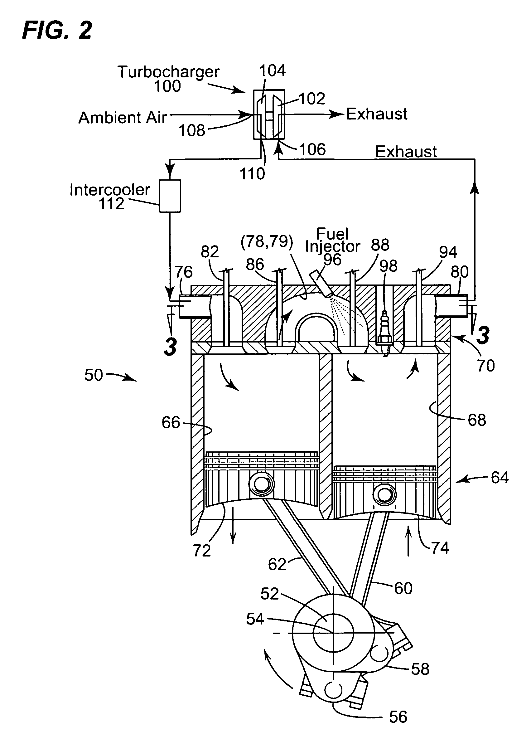
[0030]The crossover passage is constructed to conduct away at least 5.3 percent of the heat energy contained in compressed gas retained in the crossover passage between closing of the crossover expansion valve during an expansion stroke of the expansion piston and opening of the crossover compression valve during a following compression stroke of the compression piston. An uninsulated passage can conduct away at least 13 percent of the heat energy. It can also be actively cooled to control the heat loss.

Problems solved by technology

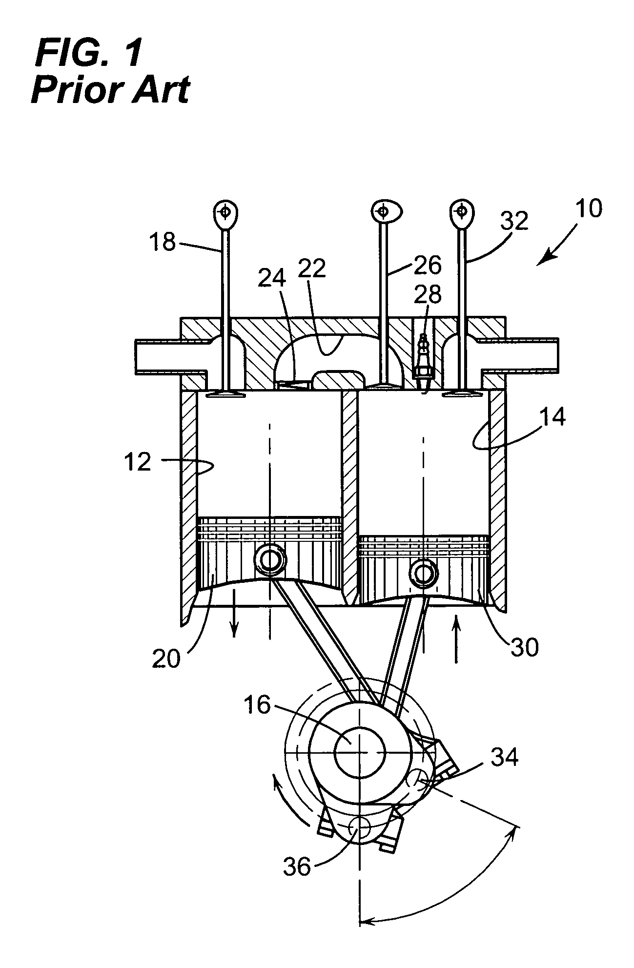
This tends to increase the size and reduce the power density of a split-cycle engine relative to a conventional engine with the same intake charge.
Problematically, the amount of boost that can be provided to the intake charge of either a conventional or split-cycle gasoline engine is limited by the point at which the fuel / air mixture is forced into premature combustion (i.e., knocking) by excessive pressures and temperatures developed within the engine during the compression stroke.
Higher boost pressures are potentially attainable, but require expensive multistage boosting and intercooling systems in prior art conventional engines.

Method used


Image

  • Knock resistant split-cycle engine
  • Knock resistant split-cycle engine
  • Knock resistant split-cycle engine

Examples


Embodiment Construction

Glossary

[0046]The following glossary of acronyms and definitions of terms used herein is provided for reference:

Air / fuel Ratio: The proportion of air to fuel in the intake charge.

Bottom Dead Center (BDC): The piston's farthest position from the cylinder head, resulting in the largest cylinder volume of the cycle.

Crank Angle (CA): The angle of rotation of the crankshaft.

Critical Pressure Ratio: The ratio of pressures which cause the flow through an orifice to achieve sonic velocity, i.e. Mach 1. It can be calculated from the following equation:

[0047]p0pc=(γ+12)γγ-1

Where:

[0048]pc=critical pressure (at throat)

[0049]p0=upstream pressure

[0050]γ=specific heat ratio.

For dry air at room temperature γ=1.4, so the critical pressure ratio is 1.893.

Compression / Expansion Cylinder Displacement Ratio: The ratio of the displacement of the compression cylinder to the expansion cylinder.

Compression Ratio: The ratio of cylinder volume at BDC to that at TDC.

Cylinder Displacement: The volume that the pi...


PUM


Abstract

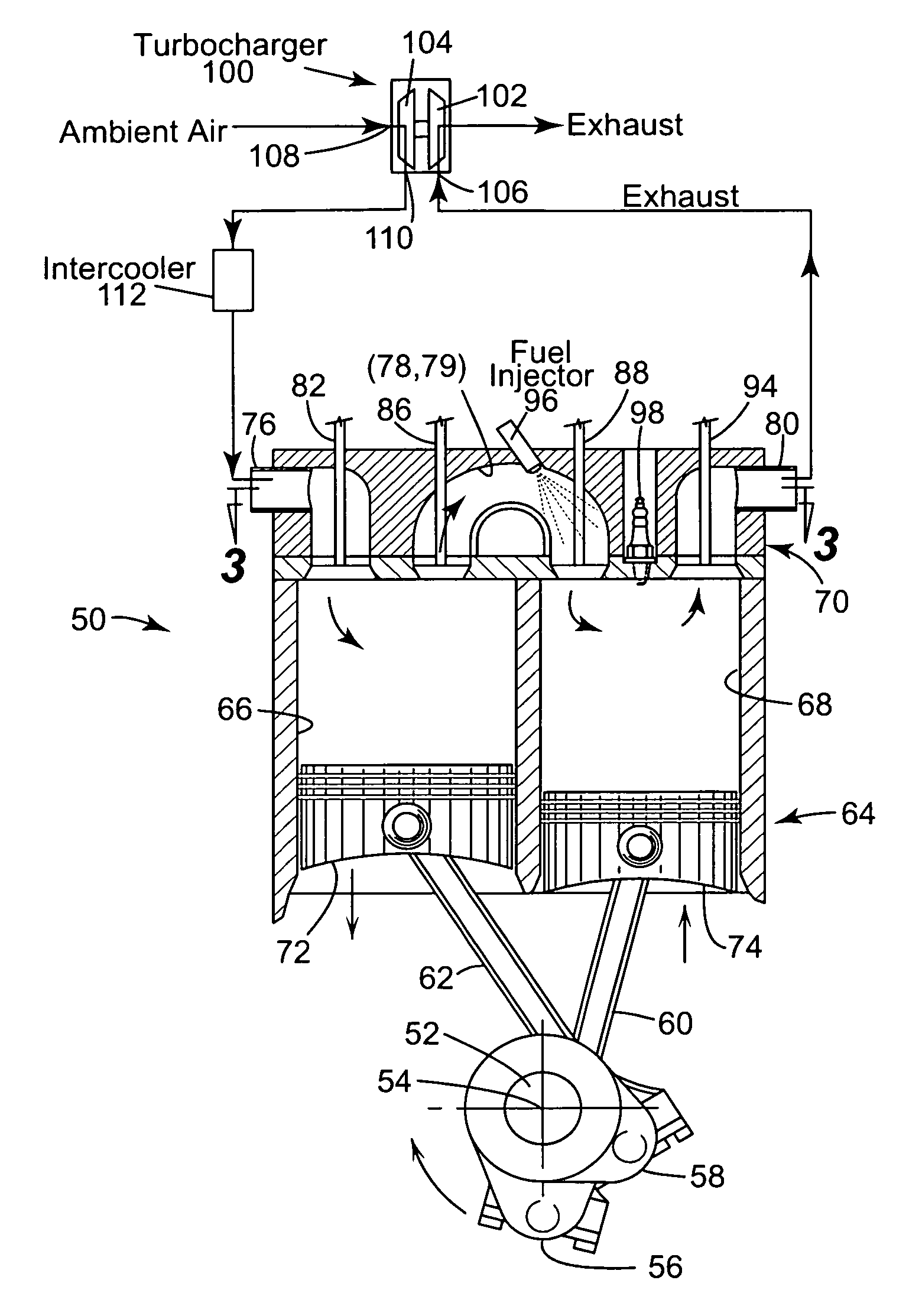
An engine has a rotatable crankshaft. A compression piston is received within a compression cylinder and operatively connected to the crankshaft such that the compression piston reciprocates through an intake stroke and a compression stroke during a single rotation of the crankshaft. An expansion piston is received within an expansion cylinder and operatively connected to the crankshaft such that the expansion piston reciprocates through an expansion stroke and an exhaust stroke during a single rotation of the crankshaft. A crossover passage interconnects the compression and expansion cylinders. The crossover passage includes a crossover compression valve and a crossover expansion valve defining a pressure chamber therebetween. A fuel injector is disposed in the pressure chamber of the crossover passage. Fuel injection from the fuel injector into the crossover passage is timed to occur entirely during the compression stroke of the compression piston.

Description

CROSS REFERENCE TO RELATED APPLICATIONS[0001]This application claims the benefit of U.S. Provisional Patent Application No. 60 / 963,742 filed Aug. 7, 2007.TECHNICAL FIELD[0002]The present invention relates to internal combustion engines. More specifically, the present invention relates to a turbocharged split-cycle engine having a pair of pistons in which one piston is used for the intake and compression strokes and another piston is used for the expansion (or power) and exhaust strokes, with each of the four strokes being completed in one revolution of the crankshaft.BACKGROUND OF THE INVENTION[0003]For purposes of clarity, the term “conventional engine” as used in the present application refers to an internal combustion engine wherein all four strokes of the well known Otto cycle (i.e., the intake, compression, expansion and exhaust strokes) are contained in each piston / cylinder combination of the engine. The term split-cycle engine as used in the present application may not have y...

Claims


Application Information

Patent Timeline
Patent Type & Authority Patents(United States)
IPC IPC(8): F02B33/22F02B5/00F02B19/00
CPCF01L1/465F01L3/20F01L9/023F02B33/22F02B2023/108F01L2003/258Y02T10/146F01L2001/34446F02B37/00F01L9/12Y02T10/12
Inventor PHILLIPS, FORD A.
Owner SKADERI GRUP LLC
Learn More