Heating control system for vehicle

a control system and vehicle technology, applied in the direction of engines/engines, refrigeration components, propulsion using engine-driven generators, etc., can solve the problems of insufficient heating ability of the configuration, increased exhaust gas and fuel consumption, and inability to fine-tune the control based on the difference between the temperature of the cooling water and the preset temperature, so as to quick increase the temperature of the cooling water and enhance fuel economy

Inactive Publication Date: 2011-11-08
TOYOTA JIDOSHA KK
View PDF23 Cites 11 Cited by
  • Summary
  • Abstract
  • Description
  • Claims
  • Application Information

AI Technical Summary

Benefits of technology

[0010]An object of the present invention is to provide a heating control system applied to vehicles such as hybrid vehicles and automobiles having an air conditioning apparatus that uses thermal energy derived from engine cooling water to perform heating, for quickly increasing the temperature of the cooling water as required to a preset temperature to promptly ensure heating performance and enhance fuel economy.

Problems solved by technology

Therefore, when high heating ability is required because of a low outside-air temperature, a problem arises that is insufficient heating ability of the configuration using the engine cooling water as a heat source.
Until the temperature of the cooling water reaches the preset temperature, the engine cannot be driven intermittently, resulting in increases in amount of exhaust gas and fuel consumption.
However, the control only makes a switch between the operation of changing the engine operating point and the operation of not changing the engine operating point.
Thus, fine control based on the difference between the cooling water temperature and the preset temperature cannot be performed, and the time that is necessary for the engine water temperature to reach a target value cannot be made sufficiently shorter.

Method used


Image

  • Heating control system for vehicle
  • Heating control system for vehicle
  • Heating control system for vehicle

Examples


Embodiment Construction

[0030]An embodiment of the present invention is hereinafter described in detail with reference to the drawings. Here, like components are denoted by like reference characters and a description thereof is not repeated.

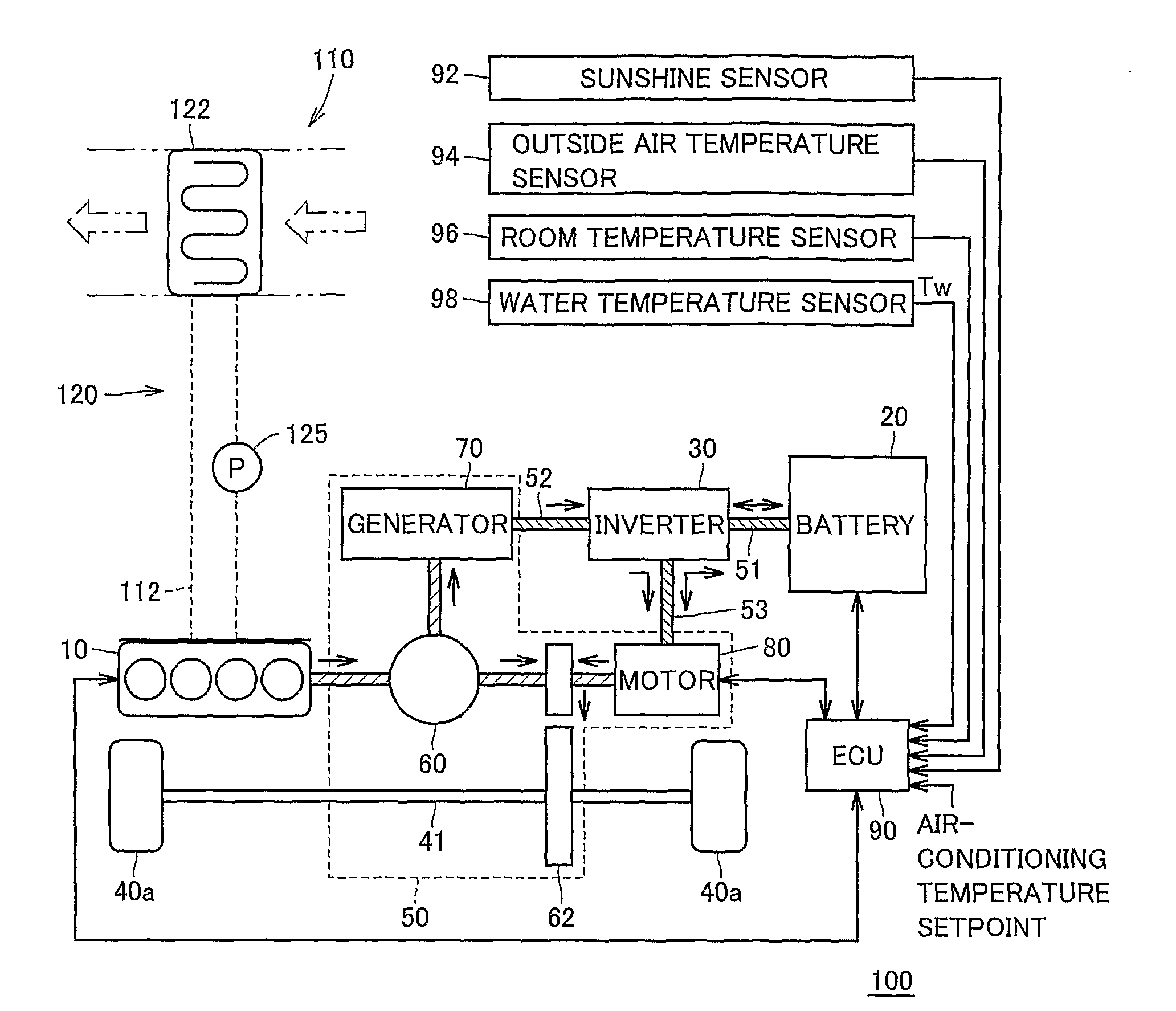
[0031]Referring to FIG. 1, a hybrid vehicle 100 having a heating control system of the present invention includes an engine 10, a battery 20, an inverter 30, wheels 40a, a transaxle 50, an electric control unit (ECU) 90, a sunshine sensor 92, an outside air temperature sensor 94, a room temperature sensor 96, a water temperature sensor 98, and an air conditioning apparatus 110.

[0032]Engine 10 uses, as an energy source, thermal energy produced by burning such a fuel as gasoline to generate driving force for wheels 40a. Battery 20 supplies DC electric power to an electric power line 51. Battery 20 is typically comprised of rechargeable secondary cell(s), like nickel hydrogen storage battery and lithium ion secondary battery.

[0033]Inverter 30 converts the DC electric power...


PUM


Abstract

A hybrid vehicle can be driven using both of respective driving forces from an engine and a motor. A heating mechanism of an air conditioning apparatus uses thermal energy from cooling water of the engine to heat the interior of a passenger compartment. An ECU takes into consideration engine efficiency from the standpoint of fuel economy enhancement to primarily determine the driving force share ratio between the engine and the motor. Further, the ECU calculates a preset temperature corresponding to a cooling water temperature necessary for desired heating as well as a control target temperature in which the preset temperature is reflected, and corrects the primarily determined driving force share ratio to increase the share of the driving force of the engine by an amount according to a deviation between the cooling water temperature measured by a water temperature sensor and the control target temperature. Heating performance can thus be ensured promptly without deterioration of fuel economy.

Description

TECHNICAL FIELD[0001]The present invention relates to a heating control system for vehicles. In particular, the present invention relates to a heating control system applied to a vehicle that has an air conditioning apparatus using thermal energy derived from cooling water of an internal combustion engine so as to perform heating.BACKGROUND ART[0002]Hybrid vehicles have recently been developed that include an internal combustion engine generating driving force from thermal energy produced by burning such a fuel as gasoline as well as an electric motor generating driving force from electrical energy. Even when the engine is stopped, the hybrid vehicle can run by driving the electric motor with electric power supplied from a battery that is charged in advance or charged with electric power generated by the engine while the vehicle is running.[0003]When the hybrid vehicle runs by using the driving force from the engine, the electric motor is driven in an auxiliary manner to enhance com...

Claims


Application Information

Patent Timeline
Patent Type & Authority Patents(United States)
IPC IPC(8): B60H1/00B60H1/06B60H1/08B60H1/22B60K6/04B60L50/16F01P7/16
CPCB60H1/004B60H1/00764B60K6/445B60H2001/00992B60L2240/34B60L2240/445B60W2510/0676Y02T10/7077Y02T10/7241Y02T10/6239B60H2001/00733Y02T10/62Y02T10/72Y02T10/7072
Inventor WATANABE, HIDETOSHIMIZU, YASUO
Owner TOYOTA JIDOSHA KK
Why Eureka
Try Eureka