Low-temperature liquefaction system for dual cycle of mixed working medium

A mixed working medium and double cycle technology, which is applied in refrigeration and liquefaction, compressors with cascading work, lighting and heating equipment, etc., can solve the problems of multiple cycle structure equipment, unreasonable temperature load distribution, complex structure, etc. , to achieve the effect of improving system safety, avoiding heat transfer temperature difference, and making the system simple and compact

Active Publication Date: 2012-08-15
TECHNICAL INST OF PHYSICS & CHEMISTRY - CHINESE ACAD OF SCI
View PDF3 Cites 1 Cited by
  • Summary
  • Abstract
  • Description
  • Claims
  • Application Information

AI Technical Summary

Problems solved by technology

[0007] According to the above description, it can be found that the circulation structure in the prior art has the problems of many devices and complex structure, and there are still unreasonable places
For example, in the technical solution disclosed in CN 101120218A, there is a downstream heat exchange of the two stream heat exchangers 108 to realize the precooling of the low-temperature refrigeration system 118, resulting in an unreasonable temperature load distribution. At the same time, there are heat exchangers in the refrigeration system 116 122 Realize self-regeneration and heat exchange, etc.

Method used


Image

  • Low-temperature liquefaction system for dual cycle of mixed working medium
  • Low-temperature liquefaction system for dual cycle of mixed working medium
  • Low-temperature liquefaction system for dual cycle of mixed working medium

Examples


Embodiment 1

[0031] The air is liquefied by using the low-temperature liquefaction system with mixed working medium double circulation provided by the present invention.

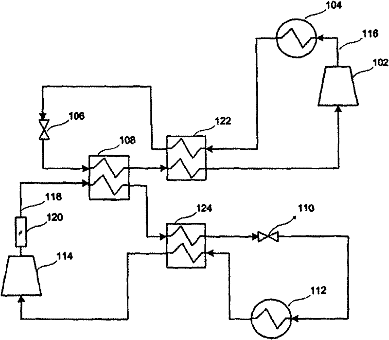
[0032] The mixed refrigerant used in the first refrigeration cycle of this embodiment 1 is composed of nitrogen, methane, ethane, propane and butane, and the mixed refrigerant is compressed by the first compressor CU1 to high temperature and high pressure , enter the first condenser AC1 to cool to normal temperature, then enter the main heat exchanger HX1 to be gradually cooled, and then enter the first throttling valve V1 through the pipeline to throttle and cool down, becoming a low-temperature and low-pressure refrigerant, and then the low-temperature and low-pressure refrigerant enters The main heat exchanger HX1 cools the high-pressure mixed refrigerant and serves as the circulating working medium in the second refrigeration cycle. After rewarming itself, it enters the compressor to complete a refrigeration cycle (th...

Embodiment 2

[0036] Example 2: Coalbed methane (or natural gas) is liquefied by using the low-temperature liquefaction system provided by the present invention using mixed working fluid double circulation.

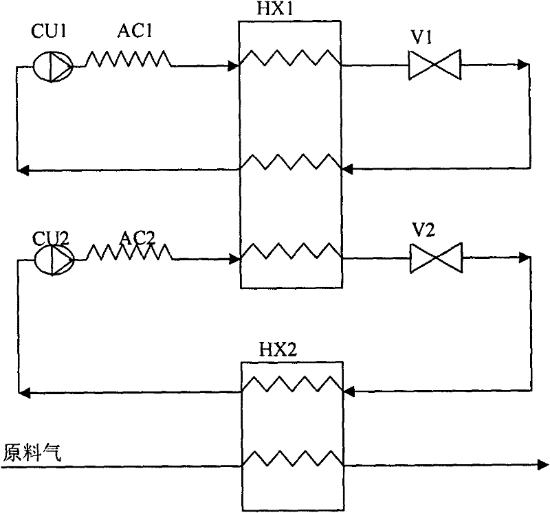
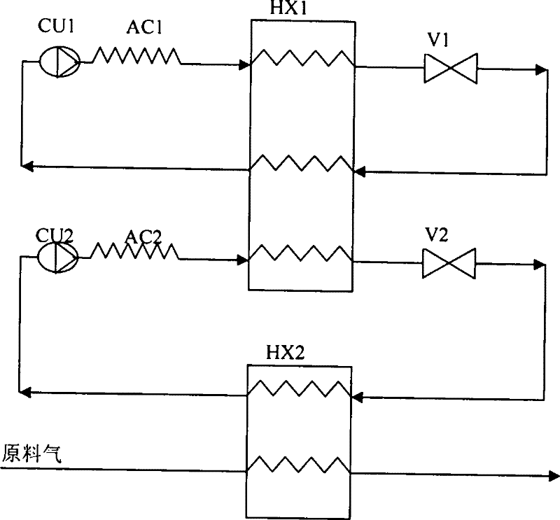
[0037] like figure 2 As shown in the low-temperature liquefaction system using mixed working medium double cycle, the connection mode of the first refrigeration cycle and the second refrigeration cycle is the same as that of embodiment 1; in this embodiment 2, the first refrigeration cycle uses the mixed refrigerant as nitrogen , methane mixed refrigerant (mixed refrigerant composed of any two or any three of nitrogen, methane, ethane, propane and butane is acceptable)

[0038] The coalbed methane after simple dedusting treatment enters the distributed heat exchanger HX2, and is cooled and liquefied by the low-temperature two-phase working fluid in the distributed heat exchanger HX2, and the liquefied coalbed methane / natural gas finally passes through the outlet of the distributed hea...


PUM


Abstract

The invention relates to a low-temperature liquefaction system for dual cycle of a mixed working medium. The system comprises a first refrigeration cycle loop, a second refrigeration cycle loop and a feed gas pipeline, wherein a mixed refrigeration working medium is used in the first refrigeration cycle loop and the first refrigeration cycle loop consists of a first compressor, a first condenser,a main heat exchanger and a first throttling valve which are connected sequentially; a non-combustible pure working medium or a non-combustible mixed working medium is used in the second refrigeration cycle loop and the second refrigeration cycle loop consists of a second compressor, a second condenser, a distributed heat exchanger and a second throttling valve which are connected sequentially; and the feed gas pipeline consists of the distributed heat exchanger and a pipeline, feed gas after dust removal treatment is connected with the inlet of the distributed heat exchanger through the pipeline, and the outlet of the distributed heat exchanger is the outlet of the liquefied feed gas. The system has the advantages of flexible design, simpleness and compactness, low cost, high operationalefficiency, high system safety because the non-combustible working medium is used in the second refrigeration cycle, and remote cold delivering.

Description

technical field [0001] The invention relates to a low-temperature liquefaction system, in particular to a low-temperature liquefaction system with double cycles of mixed working fluid. Background technique [0002] The cryogenic mixed working medium refrigeration technology using heat recovery measures has been widely used in the liquefaction of natural gas since the 1970s, and has become the leading technology in the field of liquefied natural gas (LNG). Due to the heat recovery measures and the use of multiple mixed working fluids composed of different boiling point components, the system efficiency is improved, and a single-stage oil-lubricating oil compressor can be used to drive to achieve low-temperature refrigeration. Therefore, this refrigeration technology has developed rapidly and can be used in the technology of small skid-mounted LNG liquefaction devices, which greatly reduces system costs and improves reliability. However, due to the particularity of liquefied ...

Claims


Application Information

Patent Timeline
Patent Type & Authority Patents(China)
IPC IPC(8): F25B7/00
Inventor 公茂琼吴剑峰董学强
Owner TECHNICAL INST OF PHYSICS & CHEMISTRY - CHINESE ACAD OF SCI
Why Eureka
Try Eureka