Bayonet type electronic connector

a technology of electronic connectors and bayonets, which is applied in the direction of contact members penetrating/cutting insulation/cable strands, coupling device connections, electric discharge lamps, etc., can solve the problems of low fabrication efficiency, the conventional solder-type method faces more and more difficulties in processing cables, and the connection wires fabricated by soldering, so as to ensure the stability of characteristic impedance, improve high-frequency attenuation, and enhance the effect of produ

Active Publication Date: 2011-11-08
WANG FENGLIANG
View PDF24 Cites 21 Cited by
  • Summary
  • Abstract
  • Description
  • Claims
  • Application Information

AI Technical Summary

Benefits of technology

[0011]In order to solve the aforementioned problems, the present invention discloses a connector for connecting electrical appliances, wherein the soldering points of a conventional solder multi-contact connector are transformed to a distinctive structure with a group of U-shaped bayonets staggered fore and aft in two rows, for clamping and piercing the core wires of the cables and closely contacting the conductors thereof, thereby achieving the purpose of omitting soldering and improving the fabricating efficiency.
[0012]The connector is featured in transforming the conventional parallel soldering points in piercing connection to U-shaped bayonets forming a right angle and staggered fore and aft in two rows, thereby preventing a short circuit from occurring in a narrow space and further ensuring the stability of characteristic impedance.

Problems solved by technology

However, with the miniaturization and micromation of connector contacts as well as the increase in the number of the contacts, a conventional solder-type method faces more and more difficulties in processing cables.
The connecting wires fabricated by soldering have the disadvantages of low fabrication efficiency and unstable electrical performance.
The conventional soldering method needs a lot of complicated manual operations such as cutting, stripping, positioning, soldering and trimming, and thus has the disadvantages of low efficiency and unstable performance and also becomes a bottleneck that troubles the connector, cable and electronic equipment manufacturers.
Therefore, the U-shaped bayonets can only be used in the situation of low frequency:
2. The U-shaped bayonets are only suitable for clamping ribbon cables; and
3. The bayonets are distributed on a single side, thus resulting in narrow space.

Method used


Image

  • Bayonet type electronic connector
  • Bayonet type electronic connector
  • Bayonet type electronic connector

Examples


Embodiment Construction

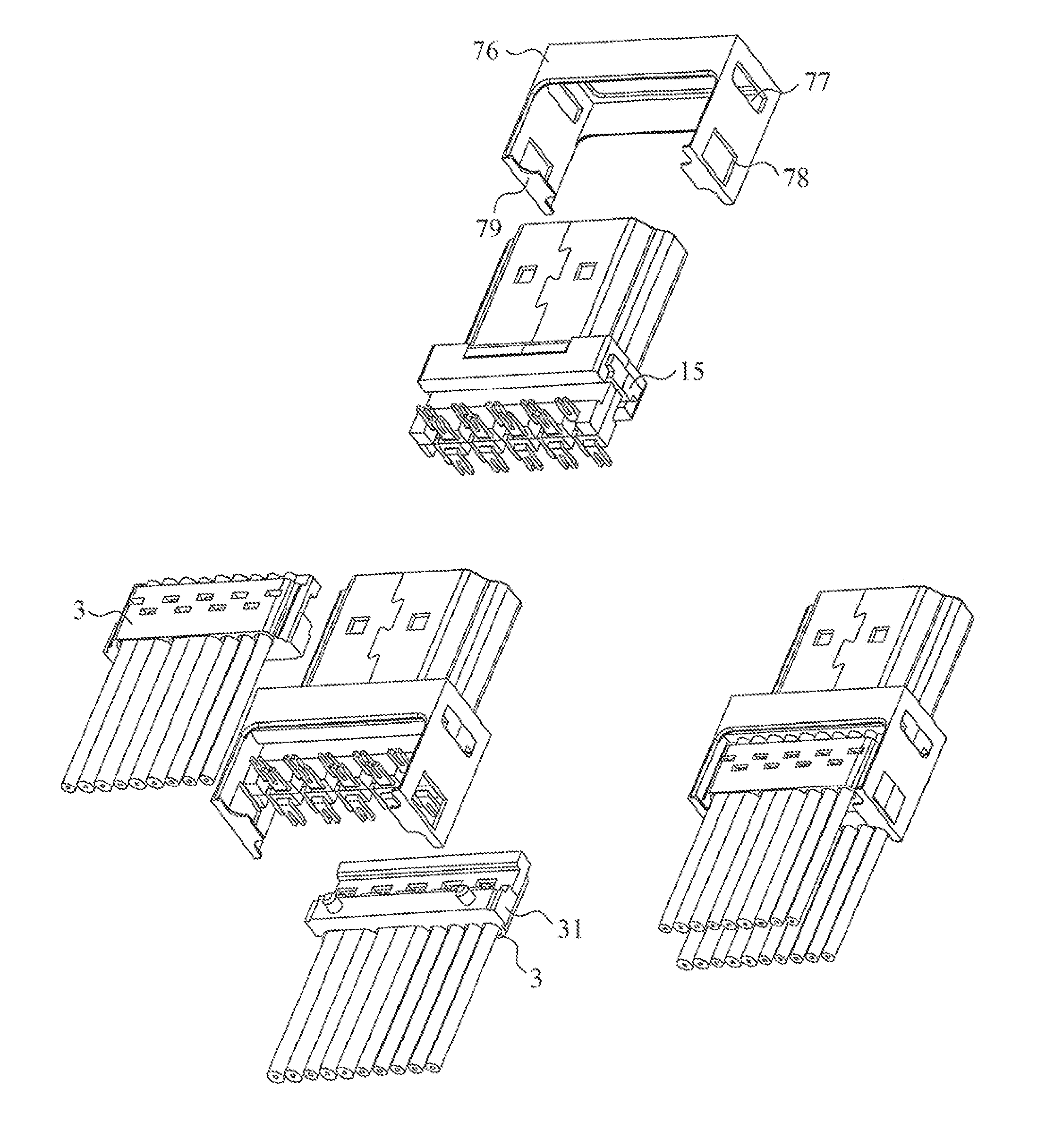
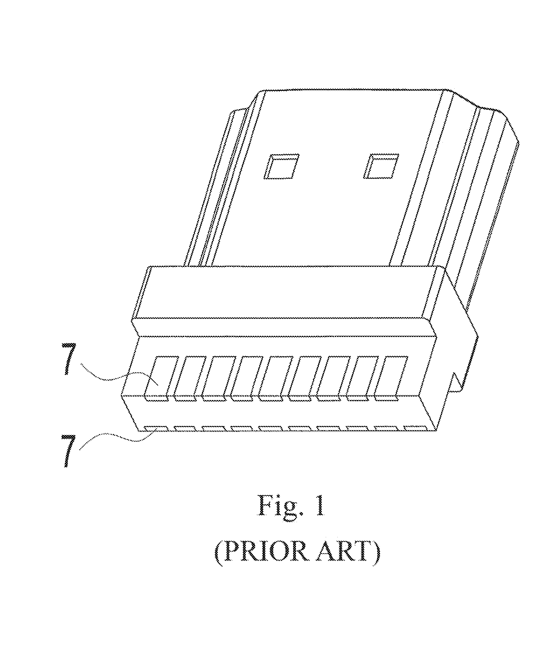
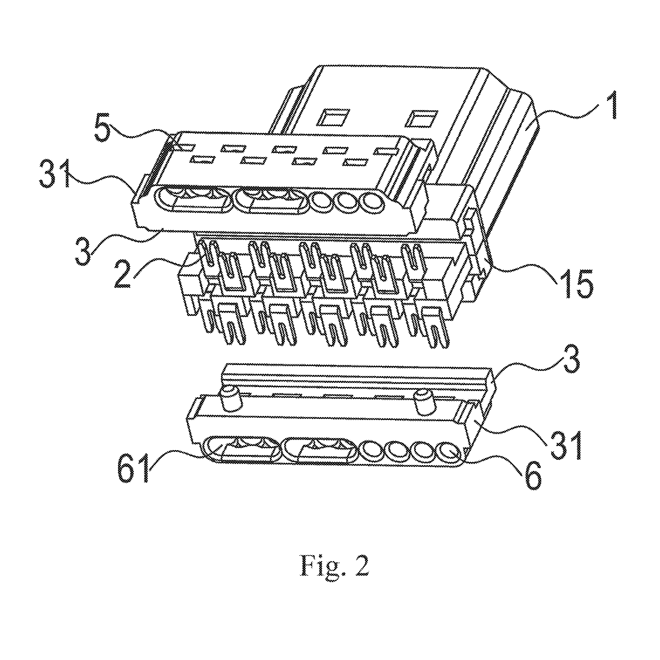
[0041]The present invention changes the metal solder points 7 of a conventional solder-type multi-contact connector to a U-shaped bayonet structure forming a right angle, and the U-shaped bayonets 2 are staggered fore and aft in two rows, so that enough functional space is ensured between the two rows of U-shaped bayonets on each surface of the connector and between the two rows of U-shaped bayonets on the upper and lower surfaces of the connector to prevent a short circuit and the stability of the characteristic impedance of the connector is ensured. FIGS. 2 and 3 are exploded views of the present invention.

[0042]The present invention is featured in that the monolithically formed plastic insulator of the conventional connector is separated into four pieces with four layers in total, i.e. insulators 12 and 13, and the metal contact plate assembly 14 is firstly injection over-molded by an insulator 13 (the insulator 13 is plastic) and then inserted into the metal shells 11 to form on...


PUM


Abstract

A bayonet type electronic connector (1) comprises metal contacts arranged on the upper and lower surfaces of the connector (1). Metal contacts all are U-shaped bayonets (2). The U-shaped bayonet's terminal forms a right angle. The adjacent U-shaped bayonets (2) on each surface are staggered fore and aft in two rows. Enough functional space is arranged between the two rows.

Description

RELATED APPLICATIONS[0001]This application is a co-pending application, which claims priority to PCT Application No. PCT / CN2009 / 000330 filed Mar. 27, 2009, which are herein incorporated by reference.BACKGROUND[0002]1. Field of Invention[0003]The present invention relates to fields of household audio-visual appliance and industrial electrical equipment. More particularly, the present invention relates to a bayonet type electronic connector.[0004]2. Description of Related Art[0005]In the fields of household audio-visual appliance, computer, industrial electrical equipment etc., along with the explosive increase of transinformation amount, a multi-contact connector has been more and more widely used, and accordingly the demands for connecting cables among equipments are daily increasing. However, with the miniaturization and micromation of connector contacts as well as the increase in the number of the contacts, a conventional solder-type method faces more and more difficulties in proc...

Claims


Application Information

Patent Timeline
Patent Type & Authority Patents(United States)
IPC IPC(8): H01R4/24
CPCH01R4/2433H01R9/035H01R13/6473H01R13/65915
Inventor WANG, FENGLIANG
Owner WANG FENGLIANG
Why Eureka
Try Eureka