Shield connector mounting structure and shield connector

a shield connector and mounting structure technology, applied in the direction of connection contact material, electrical apparatus casing/cabinet/drawer, coupling device connection, etc., can solve the problem of not stabilizing a contact load, and achieve the effect of high-reliability sealing structur

Inactive Publication Date: 2011-11-08
SUMITOMO WIRING SYST LTD
View PDF8 Cites 12 Cited by
  • Summary
  • Abstract
  • Description
  • Claims
  • Application Information

AI Technical Summary

Benefits of technology

[0012]According to the above, the connecting portion of the shield shell is bolt-fastened to the bottom wall of the mounting recess formed in the mating member. Thus, a contact load of the connecting portion on the bottom wall of the mounting recess can be increased more than that brought about by spring contact, and the connecting portion of the shield shell can be reliably brought into contact with the bottom wall of the mounting recess. Therefore, a highly reliable grounding structure is realized.
[0015]Further, according to the above, the seal ring is inserted between the outer peripheral wall of the mounting projection of the housing and the inner peripheral wall of the mounting recess while being compressed in the direction orthogonal to the longitudinal direction. With this arrangement, a direction of resilient deformation of the seal ring is in an orthogonal relationship to the bolt fastening direction (longitudinal direction). Thus, even if the connecting portion of the shield shell is bolt-fastened at a position very close to the seal ring, bolt fastening hardly affects a sealing property of the seal ring, thereby realizing a highly reliable sealing structure.

Problems solved by technology

However, the spring contact may not stabilize a contact load and, hence, improvement has been necessary.

Method used


Image

  • Shield connector mounting structure and shield connector
  • Shield connector mounting structure and shield connector
  • Shield connector mounting structure and shield connector

Examples


Embodiment Construction

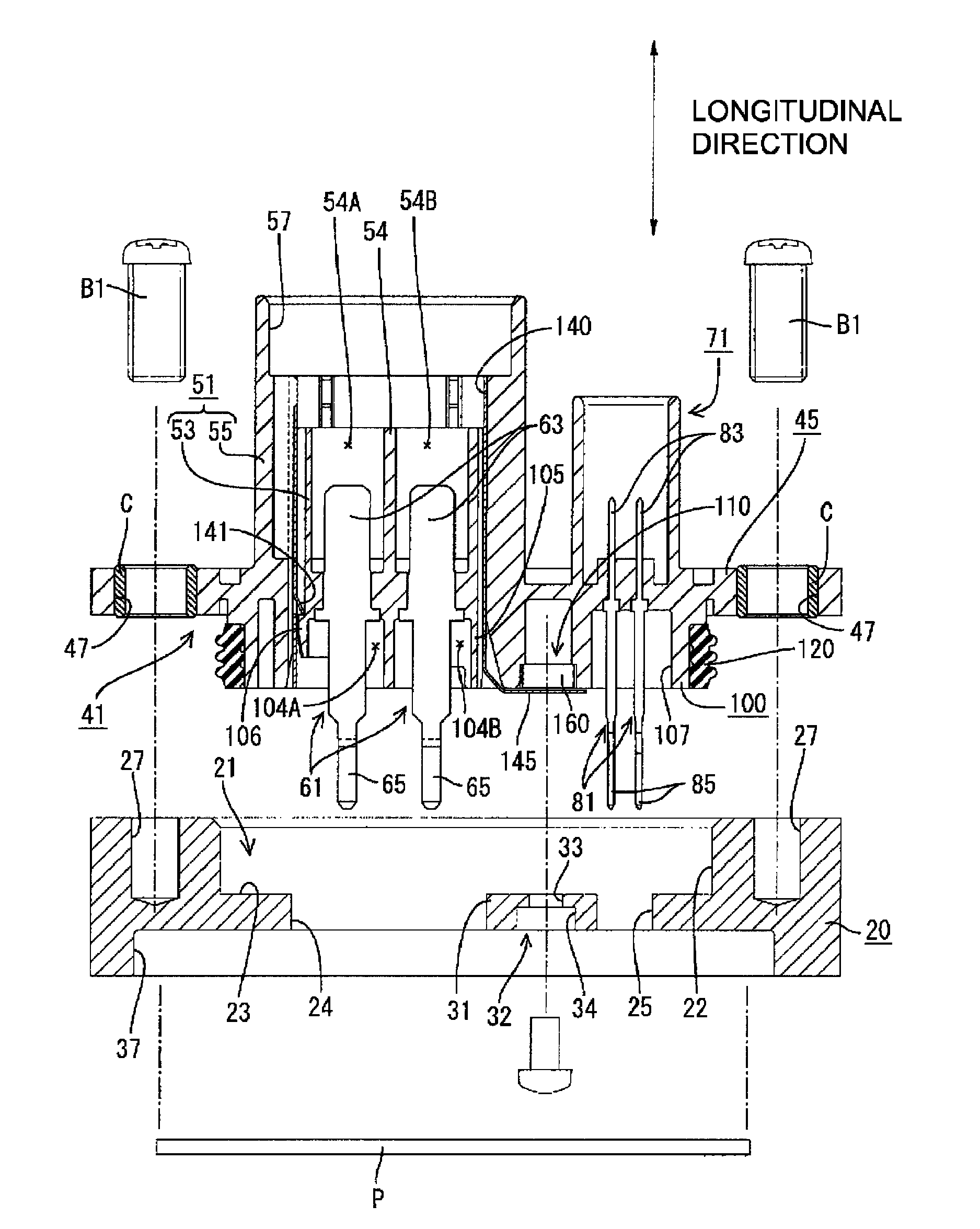
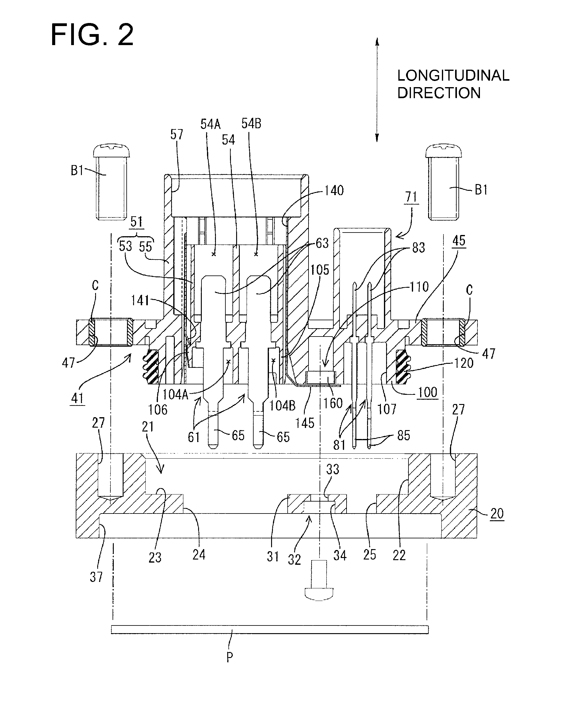
[0029]A connector in accordance with the invention is described with reference to FIGS. 1 to 11. In the following description, a direction substantially orthogonal to a base 45 of a housing 41 (vertical direction in FIG. 2) is referred to as a longitudinal direction. Further, the upper side of the base 45 in FIG. 2 is called the top and the lower side thereof in FIG. 2 (side toward a device) is called an under side.

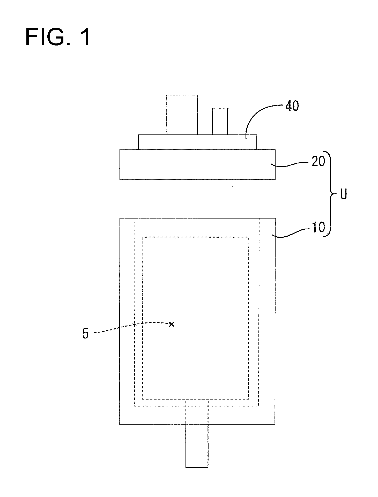
[0030]A conductive case U shown in FIG. 1 includes a metallic (e.g. aluminum die-cast, etc.) main body 10 and a metallic (e.g. aluminum die-cast, etc.) lid 20. An opening is formed in the upper surface of the main body 10, and a device (e.g. induction motor of an inverter type compressor in an automotive air conditioner) 5 can be accommodated in the opening. The opening of the main body 10 is closed by the lid 20, and the shield connector 40 is to mounted on the top side of the lid 20. Specifically, the lid 20 is formed with a mounting recess 21 and screw holes 27 adjacen...


PUM


Abstract

A shield connector (40) includes a housing with a base (45) to be mounted into a metallic mating member. A connector fitting (51) is formed on a top side of the base (45) and a mounting projection (100) is formed on an under side of the base (45). A shield shell (140) is mounted between an inner tube (53) and an outer tube (54) of the connector fitting (51). A nut accommodating portion (110) is formed in the mounting projection (100) of the housing (41) and a nut 160 is mounted in the nut accommodating portion (110) to be freely movable in the longitudinal direction. A connecting portion (145) extends to close an opening of the nut accommodating portion (110) while being bent sideways at a rear end of the shield shell (140) in the longitudinal direction.

Description

BACKGROUND OF THE INVENTION[0001]1. Field of the Invention[0002]The invention relates to a shield connector to be mounted in a case of an electrical device and a shield connector mounting structure.[0003]2. Description of the Related Art[0004]Japanese Unexamined Patent Publication No. 2008-41600 discloses a shield connector including a shield shell. The connector is intended to supply power to a device such as a motor housed in a metallic case in an electric vehicle or the like. The shield shell is grounded to the metal case by bringing a spring piece on the shield shell into contact with the aluminum die-cast metallic case. However, the spring contact may not stabilize a contact load and, hence, improvement has been necessary. A seal ring provides sealing (watertightness) between the shield connector and the metallic case. Thus, a grounding structure needs to be revised to satisfy a desired sealing property.[0005]The invention was developed in view of the above situation and an obj...

Claims


Application Information

Patent Timeline
Patent Type & Authority Patents(United States)
IPC IPC(8): H01R13/648
CPCH01R13/658H01R13/746H05K5/0039H01R13/6585H01R13/6591H01R13/5202H01R13/6584H01R13/6595
Inventor UCHIDA, MASASHI
Owner SUMITOMO WIRING SYST LTD
Why Eureka
Try Eureka