
Capsular intraocular lens implant having a refractive liquid therein

a technology of intraocular lens and liquid refractive lens, which is applied in the field of accommodating intraocular lens implants, can solve the problems of affecting the ability of the eye to properly focus an image upon the retina, increasing the focal length of the eye, and unable to achieve the ability, so as to achieve safe and effective treatment and safe long-term use of the eye

Inactive Publication Date: 2011-11-08
ABBOTT MEDICAL OPTICS INC
View PDF366 Cites 82 Cited by
  • Summary
  • Abstract
  • Description
  • Claims
  • Application Information

AI Technical Summary

Benefits of technology

[0015]The IOL of the present invention addresses this need because it provides a lightweight accommodating IOL, containing a highly refractive material therein, which is safe for long term use in an eye. The present invention presents a significant advance in the art because it provides an IOL for the safe and effective treatment of refractive errors in combination with other defects such as cataracts.
[0016]In more detail, the IOL comprises a resilient optic formed of a highly refractive material operably coupled to a flexible optic positioning member to change shape in response to ciliary body movement, i.e., contraction and retraction of the ciliary body. When the ciliary body relaxes or retracts, it causes the zonules to elongate and exert a tensional pull upon the IOL. Thus, the IOL becomes discoid in shape and allows the viewer to focus upon objects located at a distant therefrom. Similarly, when the ciliary body contracts, it becomes thicker and causes the zonules to ease the tensional pull. Thus, the IOL becomes spheroid in shape and allows the viewer to focus upon objects located near to the viewer. As noted above, the optic is formed of refractive material that has an index of refraction of from about 1.36 to 1.5 or higher (e.g., hydrocarbon oil, silicone oil, or silicone gel). In one type of IOL in accordance with the invention, use is made of a pre-formed capsule having a thin, continuous wall wherein the refractive material is enveloped.
[0017]The optic maybe coupled with various optic positioning members commonly used in IOL construction depending upon the user's eyesight. The optic may be positioned within the capsule of the eye such that the anterior surface of the optic faces either the anterior or the posterior portion of the eye. When the optic is positioned to face the posterior portion of the eye, the optic will vault posteriorly in response to contraction of the ciliary body. However, the change in the radius of curvature of the optic will counteract the effects of the negative accommodation, i.e., movement of the optic posteriorly. The resiliency of the optic permits a small change in radius of curvature which, when coupled with the relatively high index of refraction of the refractive material, results in an optic having greater light-bending properties than conventional optics.
[0020]Yet another preferred embodiment of the IOL of the present invention includes an optic positioning member comprised of an enclosed flexible bag having resilient fill material therein. The enclosed flexible bag presents an anterior segment and an opposed posterior segment, each having an optic. The optic positioning member is pre-formed to present opposed optic surfaces, hence, the optics are integral with the optic positioning member. The resilient fill material is comprised of the same refractive material used in the above-referenced resilient optic construction. This embodiment also functions similarly to the IOLs discussed above because the anterior optic surface moves anteriorly and the posterior optic surface moves posteriorly in response to contraction of the ciliary body. The optic surfaces of the flexible bag optic positioning member present a small change in the radius of curvature (e.g., 5-4.6 mm) from the accommodated to disaccommodated shapes, coupled with high refractive power thereby permitting retinal receipt of an observed image.

Problems solved by technology

Refractive errors in the eye affect one's ability to properly focus an image upon the retina due to a change in the refractive medium of the eye, e.g., the cornea, the natural crystalline lens, or both.
The refractive errors pertinent to this application include myopia, hyperopia, and presbyopia.
A myopic lacks the ability to focus an image located at a distance from the viewer because the cornea has become elongated, thereby increasing the eye's focal length.
A hyperopic lacks the ability to focus on objects located near the viewer because the cornea is not elongated enough or is too flat, and cannot refract light properly upon the retina.
Presbyopia is another type of refractive error which results in the inability of the eye to focus because of hardening of the natural crystalline lens.
Possible side effects of refractive surgery include irregular astigmatism, infection, or haze formation which could result in permanent changes in the cornea and possible loss of best-corrected visual acuity.
Furthermore, none of these refractive surgeries can be used to correct all of the above-referenced refractive errors.
Problems such as dislocation after implantation forced abandonment of this approach, and for some period thereafter IOLs were implanted in the anterior chamber of the eye.
None of these IOLs have accommodation capability.
Although the Tennant IOL claims to possess accommodation capabilities, it presents the same disadvantages as other anterior chamber lenses.
This IOL functions in much the same manner as the natural crystalline lens, but may cause bleeding because it requires sutures.
Since accommodation for near vision is the normal status of the capsule, the Levy IOL's haptics are loaded, reducing the fatigue life of the springlike haptics.
This will eventually lead to pressure necrosis of the ciliary body.
The Smith IOL is faulty because the structure of the lens members makes surgical implantation thereof extremely difficult to accomplish, even for highly skilled surgeons.
Furthermore, the Smith IOL requires sutures which increases the risk of bleeding.

Method used


Image

  • Capsular intraocular lens implant having a refractive liquid therein
  • Capsular intraocular lens implant having a refractive liquid therein
  • Capsular intraocular lens implant having a refractive liquid therein

Examples


Embodiment Construction

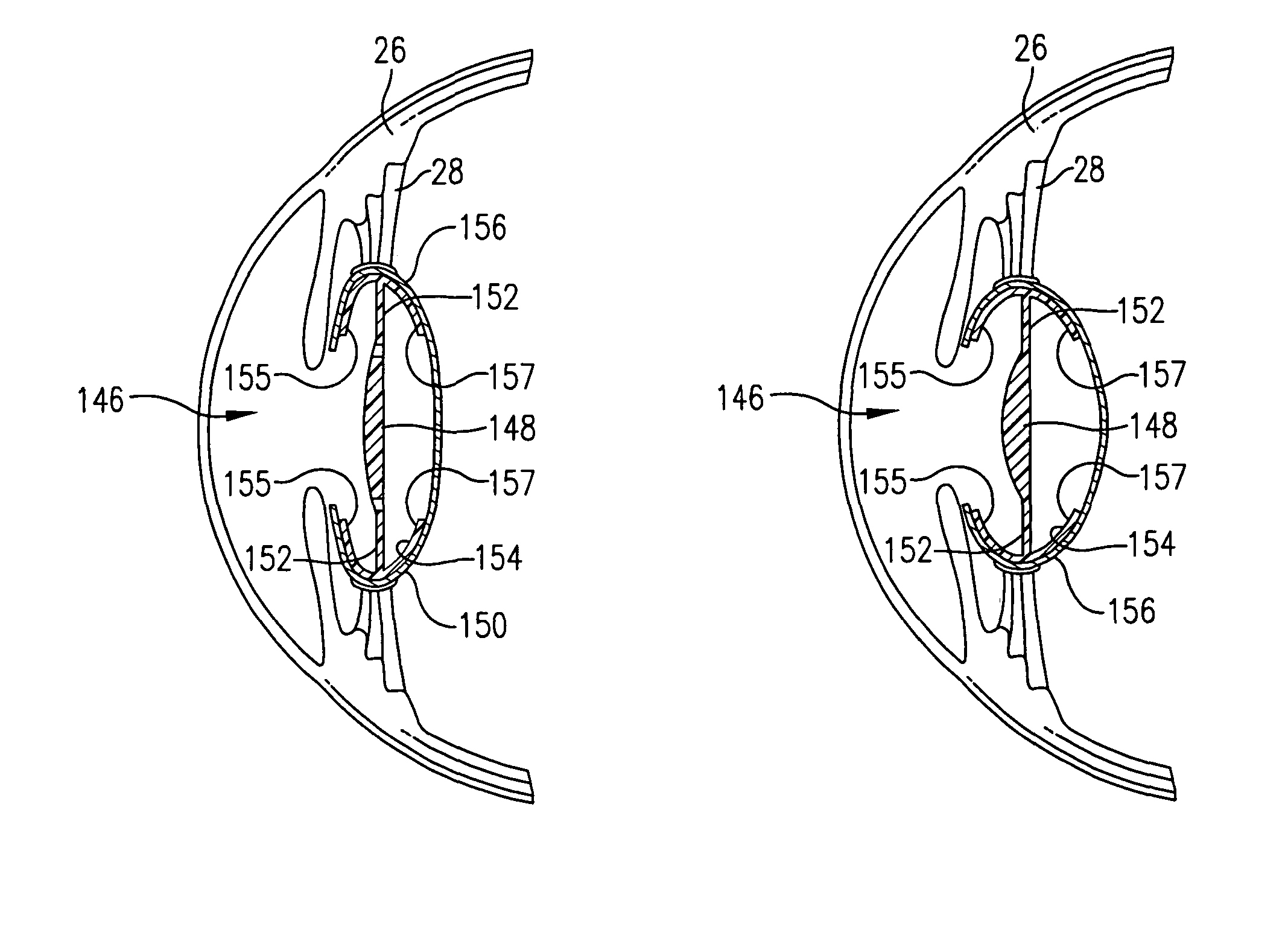
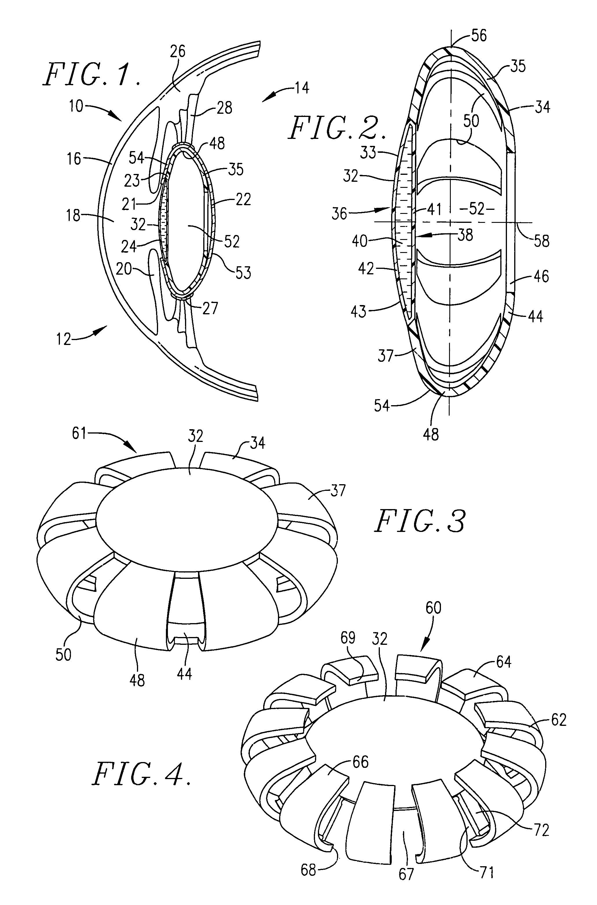
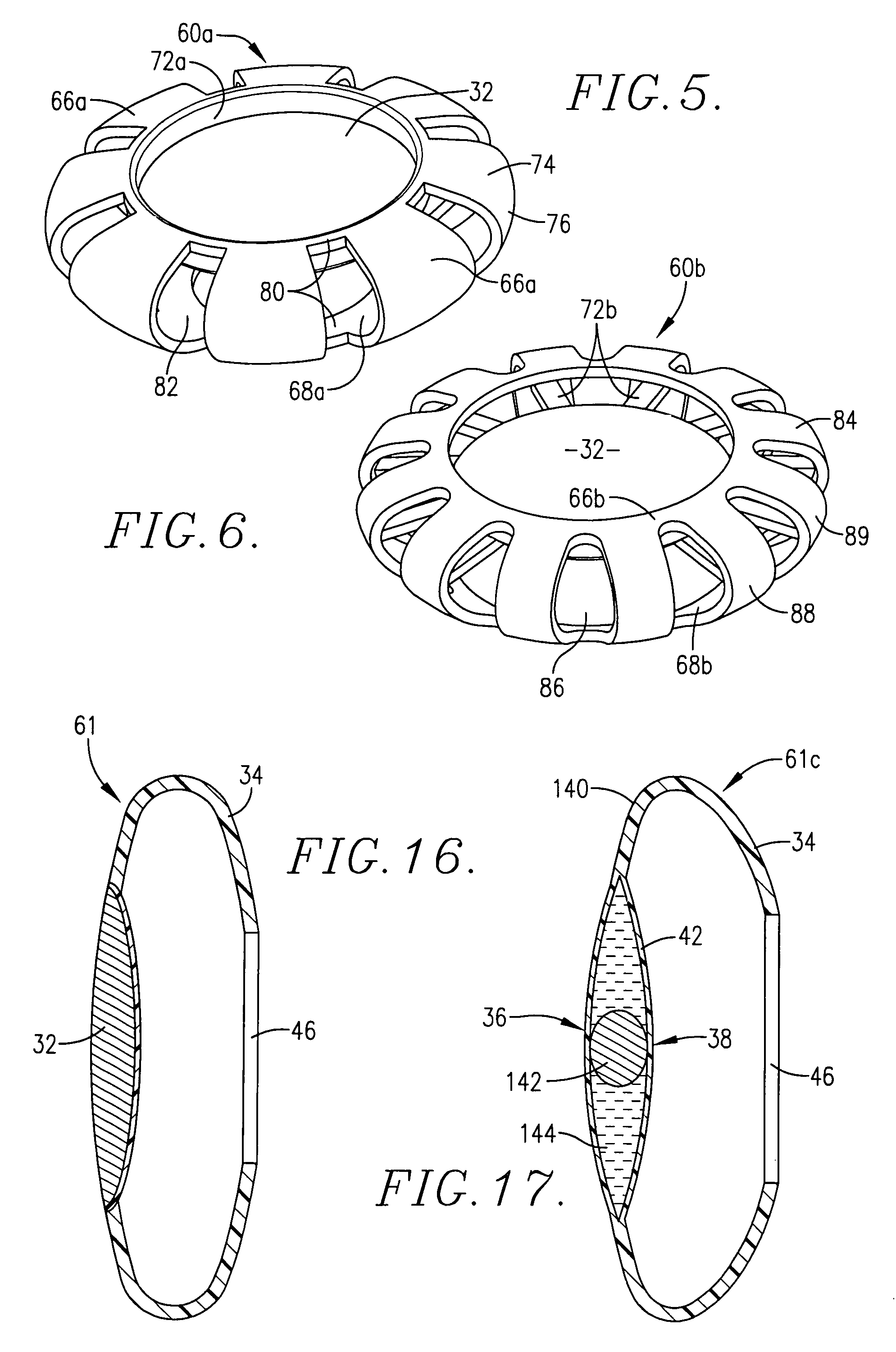
[0048]Referring now to the drawings, the present invention is in the form of an IOL for surgical replacement of the natural crystalline lens in the treatment of refractive error in the human eye. FIG. 1 shows the various components of the human eye 10 pertinent to this invention. Briefly, the eye 10 includes an anterior portion 12 and a posterior portion 14. The anterior portion 12 of the eye 10 is covered by a cornea 16 which encloses and forms an anterior chamber 18. The anterior chamber 18 contains aqueous fluid and is bounded at the rear by an iris 20. The iris 20 opens and closes to admit appropriate quantities of light into the inner portions of the eye 10. The eye 10 also includes a capsule 22 which ordinarily contains the natural crystalline lens (which would be located at numeral 24 in the natural, unmodified eye). The eye 10 includes a ciliary muscle or body 26 having zonular fibers 28 (also referred to as zonules) which are attached to the eye 10. The vitreous humor 30 is...


PUM


Abstract

An intraocular lens having a light-transmitting optic (32, 94a, 94b, 142, 148, 216) comprised of a synthetic light-refractive material (40, 102) operably coupled with a flexible optic positioning member (34, 62, 74, 84, 100, 150, 210) to refract light onto the retina in order to correct refractive errors in the eye (10). The refractive material has an index of refraction of from about 1.36 to 1.5 or higher. The optic positioning member (34, 62, 74, 84, 100, 150, 210) is constructed of a flexible synthetic resin material such as polymethylmethacrylate and permits focusing upon objects located near to and far from the viewer. The optic (32, 94a, 94b, 142, 148, 216) of the present invention possess greater refractive capability than optics conventionally used in IOL construction, and permits retinal receipt of the image being viewed in order to correct refractive errors.

Description

RELATED APPLICATIONS[0001]This application is a continuation-in-part application of U.S. patent application Ser. No. 10 / 280,918, filed on Oct. 25, 2002 now abandoned, incorporated herein by reference.BACKGROUND OF THE INVENTION[0002]1. Field of the Invention[0003]The present invention relates to an accommodating intraocular lens implant (IOL), containing a refractive material therein, for surgical replacement of the natural crystalline lens to treat refractive errors in the human eye.[0004]2. Description of the Prior Art[0005]Refractive errors in the eye affect one's ability to properly focus an image upon the retina due to a change in the refractive medium of the eye, e.g., the cornea, the natural crystalline lens, or both. The refractive errors pertinent to this application include myopia, hyperopia, and presbyopia. A myopic lacks the ability to focus an image located at a distance from the viewer because the cornea has become elongated, thereby increasing the eye's focal length. ...

Claims


Application Information

Patent Timeline
Patent Type & Authority Patents(United States)
IPC IPC(8): A61F2/16
CPCA61F2/1613A61F2/1648A61F2/1635A61F2250/0053A61F2002/1682A61F2210/0014
Inventor WOODS, RANDALLSCHULZ, ROBERT
Owner ABBOTT MEDICAL OPTICS INC
Learn More